Components
COMPONENTS
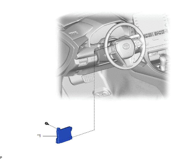
ILLUSTRATION
|
*1 | AIR CONDITIONING AMPLIFIER ASSEMBLY |
- | - |
Installation
INSTALLATION
PROCEDURE
1. INSTALL AIR CONDITIONING AMPLIFIER ASSEMBLY
(a) Connect each connector.
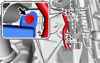
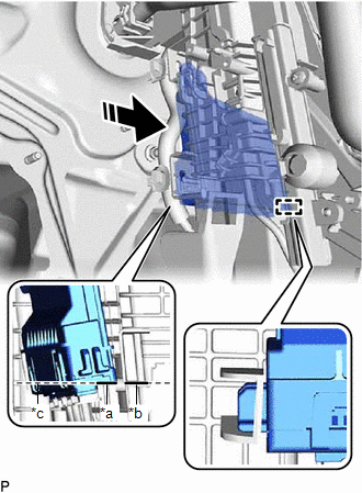
(b) Align the lower part of the air conditioning amplifier assembly with the rib of the air conditioner unit assembly and engage the guide as shown in the illustration.
|
*a | Lower Part of Air Conditioning Amplifier Assembly |
|
*b | Rib of Air Conditioner Unit Assembly |
|
*c | Align |
 |
Install in this Direction |
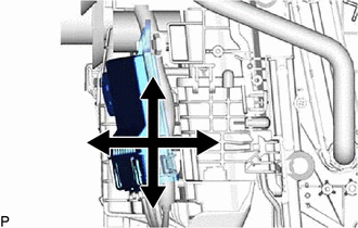
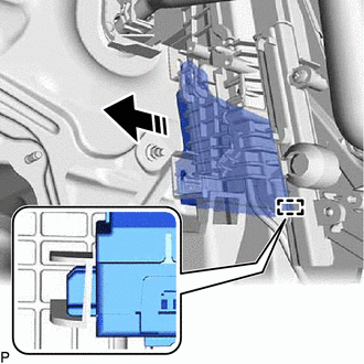
| (c) Move the air conditioning amplifier assembly in each direction shown in the illustration to check that the guide is securely engaged. |
|
(d) Install the air conditioning amplifier assembly with the screw.
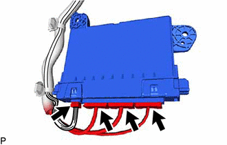
(e) Engage each clamp.
2. INSTALL ACCELERATOR PEDAL (for 2GR-FKS)
Click here

3. INSTALL ACCELERATOR PEDAL SENSOR ASSEMBLY (for A25A-FXS)
Click here
Removal
REMOVAL
PROCEDURE
1. REMOVE ACCELERATOR PEDAL SENSOR ASSEMBLY (for A25A-FXS)
Click here

2. REMOVE ACCELERATOR PEDAL (for 2GR-FKS)
Click here
3. REMOVE AIR CONDITIONING AMPLIFIER ASSEMBLY
| (a) Disengage each clamp. |
|
(b) Remove the screw.
(c) Disengage the guide as shown in the illustration.
 | Remove in this Direction |
| (d) Disconnect each connector to remove the air conditioning amplifier assembly. |
|
Toyota Avalon (XX50) 2019-2022 Service & Repair Manual > Sfi System: Random/Multiple Cylinder Misfire Detected (P030000,P030027,P030085-P030600)
DESCRIPTION When the engine misfires, high concentrations of hydrocarbons (HC) enter the exhaust gas. Extremely high hydrocarbon concentration levels can cause an increase in exhaust emission levels. Extremely high concentrations of hydrocarbons can also cause increases in the three-way catalytic co ...