Installation
INSTALLATION
PROCEDURE
1. INSTALL AIR CONDITIONER PRESSURE SENSOR
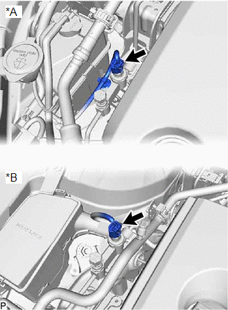
(a) Remove the vinyl tape from the air conditioning tube and accessory assembly.
(b)
Sufficiently apply compressor oil to a new air conditioner pressure
sensor and the fitting surface of the air conditioner pressure sensor.
|
Refrigerant | Compressor Oil |
|
for Gasoline Model | ND-OIL 12 or equivalent |
|
for HV Model | ND-OIL 11 or equivalent |
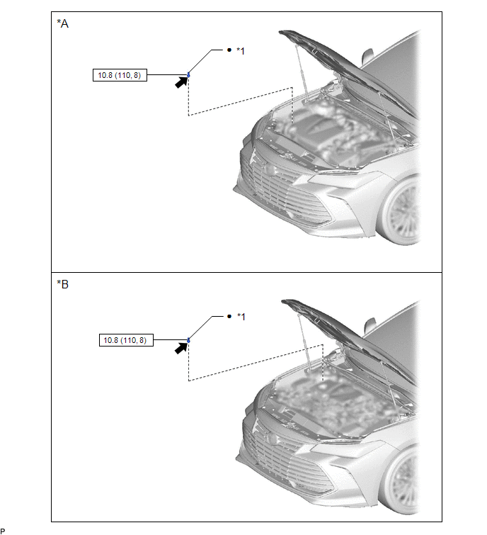
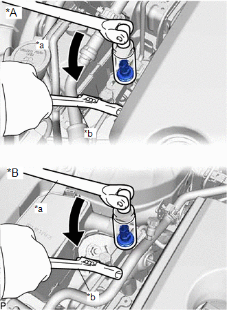
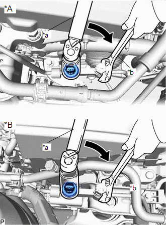
| (c) Using a 27 mm deep socket wrench, install the air conditioner pressure sensor as shown in the illustration.
Torque: 10.8 N·m {110 kgf·cm, 8 ft·lbf} |
 |
|
*A | for HV Model | |
*B | for Gasoline Model | |
*a | Turn | |
*b | Hold | | |
(d) Connect the connector.
2. CHARGE AIR CONDITIONING SYSTEM WITH REFRIGERANT
Click here 
3. WARM UP ENGINE (for Gasoline Model)
Click here 
4. WARM UP COMPRESSOR (for HV Model)
Click here 
5. INSPECT FOR REFRIGERANT LEAK
Click here 
On-vehicle Inspection
ON-VEHICLE INSPECTION
PROCEDURE
1. INSPECT AIR CONDITIONER PRESSURE SENSOR
(a) Check the wire harness.
(1) Disconnect the A15 air conditioner pressure sensor connector.
(2) Disconnect the G36 air conditioning amplifier assembly connector.
(3) Measure the resistance according to the value(s) in the table below.
Standard Resistance:
|
Tester Connection | Condition |
Specified Condition |
|
A15-1 (-) - G36-3 (SG-4) |
Always | Below 1 Ω |
|
A15-2 (PR) - G36-24 (PRE) |
Always | Below 1 Ω |
|
A15-3 (+) - G36-6 (S5-3) |
Always | Below 1 Ω |
|
A15-1 (-) or G36-3 (SG-4) - Other terminals and body ground |
Always | 10 kΩ or higher |
|
A15-2 (PR) or G36-24 (PRE) - Other terminals and body ground |
Always | 10 kΩ or higher |
|
A15-3 (+) or G36-6 (S5-3) - Other terminals and body ground |
Always | 10 kΩ or higher |
If the resistance is not as specified, repair or replace the wire harness.
(4) Connect the G36 air conditioning amplifier assembly connector.
(5) Turn the power switch*1 or engine switch*2 to on (IG).
(6) Measure the voltage according to the value(s) in the table below.
Standard Voltage:
|
Tester Connection | Condition |
Specified Condition |
|
*1: for HV Model
*2: for Gasoline Model |
|
A15-3 (+) - Body ground |
Power switch on (IG)*1 |
4.75 to 5.25 V |
|
Engine switch on (IG)*2 |
If the voltage is not as specified, repair or replace the wire harness or replace the air conditioning amplifier assembly.
(b) Check the air conditioner pressure sensor.
(1) Connect the A15 air conditioner pressure sensor connector.
(2) Install a manifold gauge set.
(3) Turn the A/C switch on.
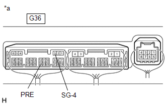
| (4) Measure the voltage according to the value(s) in the table below.
HINT: Check from the rear of the connector while it is connected to the air conditioning amplifier assembly.
Standard Voltage: |
Tester Connection | Condition |
Specified Condition | |
G36-24 (PRE) - G36-3 (SG-4) |
Refrigerant pressure: Normal pressure (less than 3025 kPa (30.8 kgf/cm2, 439 psi) and more than 176 kPa (1.8 kgf/cm2, 26 psi)) |
0.74 to 4.61 V | If the voltage is not as specified, replace the air conditioner pressure sensor. |
 |
|
*a | Component with harness connected
(Air Conditioning Amplifier Assembly) | | |
