Components
COMPONENTS
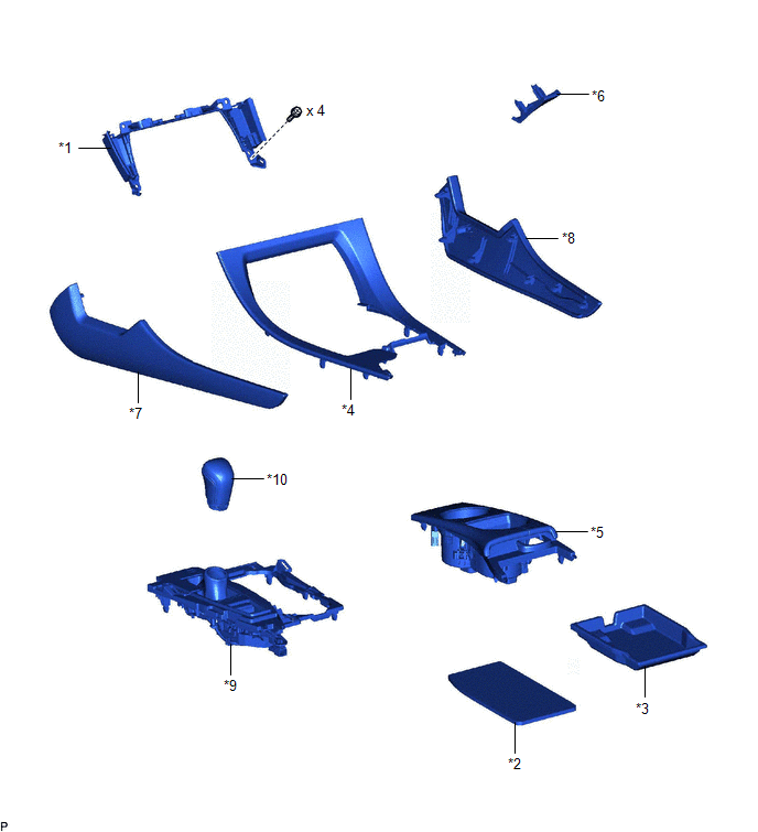
ILLUSTRATION
|
*1 | CENTER INSTRUMENT CLUSTER FINISH PANEL SUB-ASSEMBLY |
*2 | CONSOLE BOX CARPET |
|
*3 | CONSOLE BOX POCKET |
*4 | CONSOLE BOX POCKET SUB-ASSEMBLY |
|
*5 | FRONT CONSOLE UPPER PANEL GARNISH |
*6 | INSTRUMENT PANEL FINISH PANEL END LH |
|
*7 | LOWER INSTRUMENT PANEL FINISH PANEL LH |
*8 | LOWER INSTRUMENT PANEL FINISH PANEL RH |
|
*9 | REAR UPPER CONSOLE PANEL SUB-ASSEMBLY |
*10 | SHIFT LEVER KNOB SUB-ASSEMBLY |
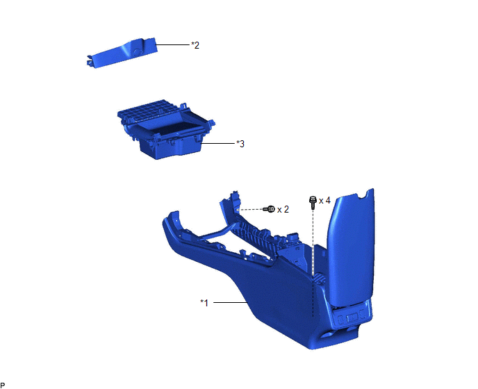
ILLUSTRATION
|
*1 | CONSOLE ASSEMBLY |
*2 | CONSOLE BOX BEZEL |
|
*3 | UPPER FRONT CONSOLE PANEL SUB-ASSEMBLY |
- | - |
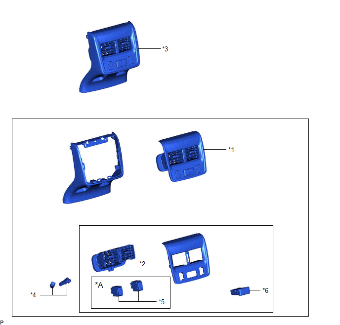
ILLUSTRATION
|
*A | w/ Seat Heater System |
- | - |
|
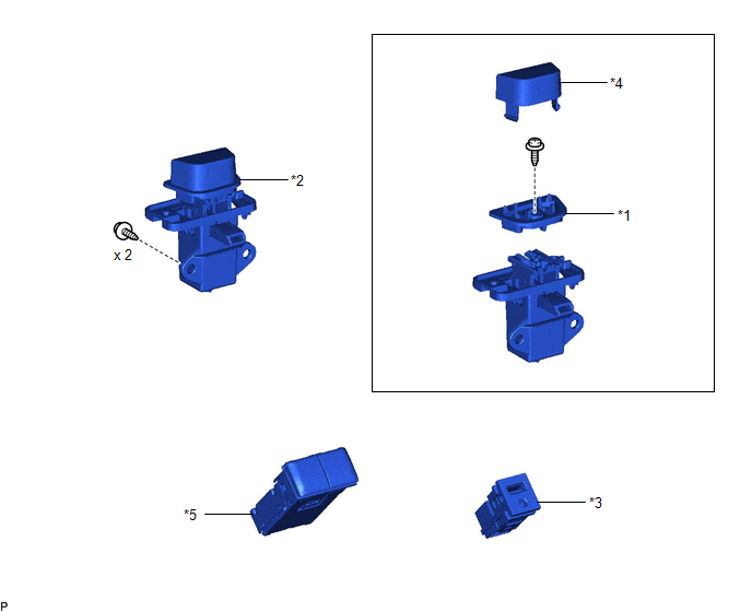
*1 | CONSOLE BOX ORNAMENT |
*2 | CONSOLE BOX REGISTER ASSEMBLY |
|
*3 | CONSOLE REAR END PANEL SUB-ASSEMBLY |
*4 | NO. 6 INTERIOR ILLUMINATION LIGHT SUB-ASSEMBLY |
|
*5 | SEAT HEATER SWITCH |
*6 | USB CHARGER SOCKET |
ILLUSTRATION
|
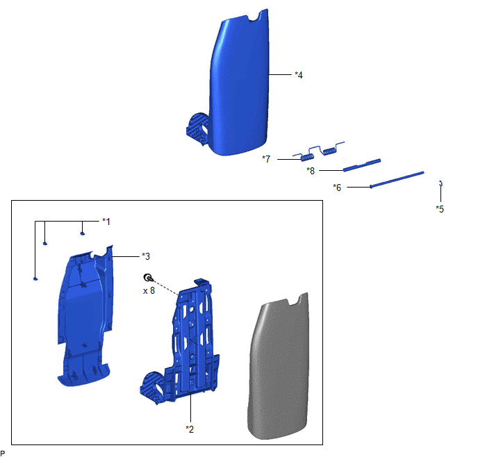
*1 | CONSOLE COMPARTMENT DOOR CUSHION |
*2 | CONSOLE COMPARTMENT DOOR HINGE SUB-ASSEMBLY |
|
*3 | CONSOLE COMPARTMENT DOOR PANEL |
*4 | REAR CONSOLE ARMREST ASSEMBLY |
|
*5 | E-RING |
*6 | CONSOLE COMPARTMENT DOOR STOPPER PIN |
|
*7 | CONSOLE BOX MOUNT BRACKET SPRING |
*8 | CONSOLE BOX SPACER |
ILLUSTRATION
|
*1 | CONSOLE COMPARTMENT DOOR HINGE RETAINER |
*2 | CONSOLE COMPARTMENT DOOR LOCK SUB-ASSEMBLY |
|
*3 | STEREO JACK ADAPTER ASSEMBLY |
*4 | UPPER CONSOLE RETAINER |
|
*5 | USB CHARGER SOCKET |
- | - |
ILLUSTRATION

|
*A | w/o Seat Heater System |
*B | w/ Seat Heater System |
|
*1 | CONSOLE BOX RETAINER |
*2 | CONSOLE BOX WIRE |
|
*3 | NO. 1 BOX SIDE PANEL |
*4 | NO. 2 BOX SIDE PANEL |
|
*5 | NO. 2 CONSOLE BOX SUPPORT |
*6 | NO. 3 CONSOLE BOX DUCT |
|
*7 | NO. 5 INTERIOR ILLUMINATION LIGHT SUB-ASSEMBLY |
- | - |
Disassembly
DISASSEMBLY
PROCEDURE
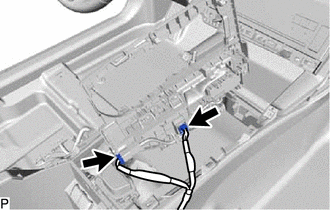
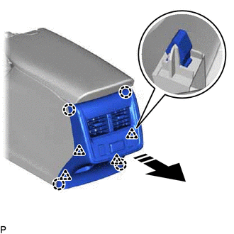
1. REMOVE CONSOLE REAR END PANEL SUB-ASSEMBLY
(a) Disengage the 4 claws and 4 clips as shown in the illustration.
 |
Remove in this Direction |
| (b) Disconnect each connector. | |
(c) Disengage the clamp to remove the console rear end panel sub-assembly.
2. REMOVE NO. 6 INTERIOR ILLUMINATION LIGHT SUB-ASSEMBLY
Click here

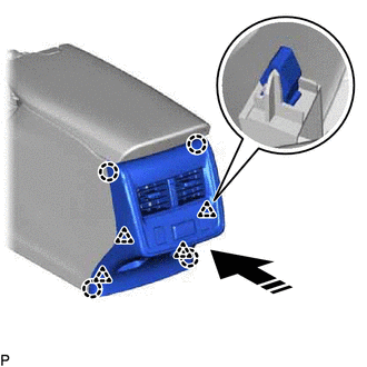
3. REMOVE CONSOLE BOX ORNAMENT
| (a) Disengage the 6 clips and 2 guides to remove the console box ornament. |
|
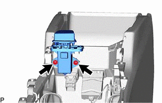
4. REMOVE USB CHARGER SOCKET (for Rear Side)
Click here
5. REMOVE SEAT HEATER SWITCH (w/ Seat Heater System)
Click here
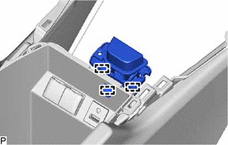
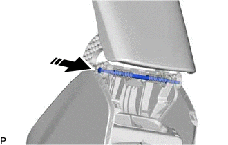
6. REMOVE CONSOLE BOX REGISTER ASSEMBLY
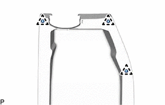
| (a) Disengage the 6 claws to remove the console box register assembly. |
|
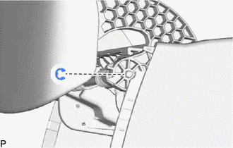
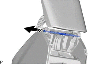
7. REMOVE REAR CONSOLE ARMREST ASSEMBLY
| (a) Disengage the 2 guides. | |
(c) Remove the console compartment door stopper pin as shown in the illustration.
|
|
Remove in this Direction |
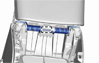
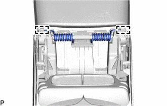
| (d) Disengage the guide to remove the console box mount bracket spring and console box spacer. |
|
(e) Remove the rear console armrest assembly as shown in the illustration.
|
|
Remove in this Direction |
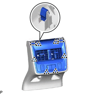
8. REMOVE CONSOLE COMPARTMENT DOOR PANEL
| (a) Disengage the 14 claws to remove the console compartment door panel. |
|
9. REMOVE CONSOLE COMPARTMENT DOOR CUSHION
| (a) Disengage the 3 clips to remove the 3 console compartment door cushions. |
|
10. REMOVE CONSOLE COMPARTMENT DOOR HINGE SUB-ASSEMBLY
| (a) Remove the 8 screws and console compartment door hinge sub-assembly. |
|
11. REMOVE CONSOLE COMPARTMENT DOOR LOCK SUB-ASSEMBLY
| (b) Disengage the 3 guides to remove the console compartment door lock sub-assembly. |
|
12. REMOVE UPPER CONSOLE RETAINER
| (a) Disengage the 2 claws to remove the upper console retainer. |
|
13. REMOVE CONSOLE COMPARTMENT DOOR HINGE RETAINER
| (b) Disengage the 2 claws to remove the console compartment door hinge retainer. |
|
14. REMOVE USB CHARGER SOCKET (for Front Side)
Click here
15. REMOVE STEREO JACK ADAPTER ASSEMBLY
Click here
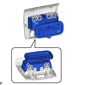
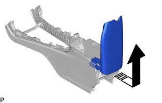
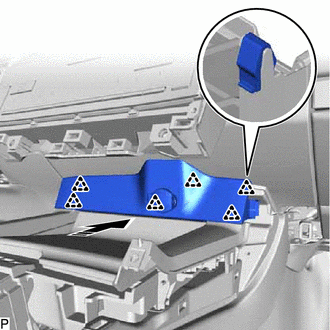
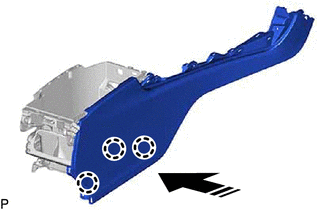
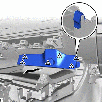
16. REMOVE NO. 2 BOX SIDE PANEL
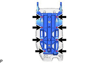
(a) Disengage the 4 claws as shown in the illustration.
|
|
Remove in this Direction |
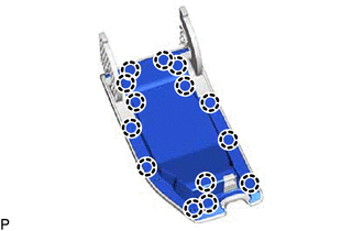
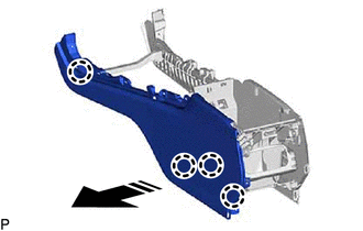
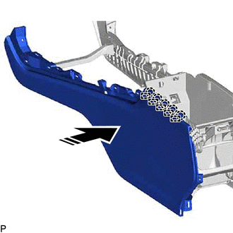
(b)
Using a moulding remover, disengage the 5 claws and 5 guides as shown
in the illustration to remove the No. 2 box side panel.
 |
Insert Moulding Remover Here |
|
|
Remove in this Direction |
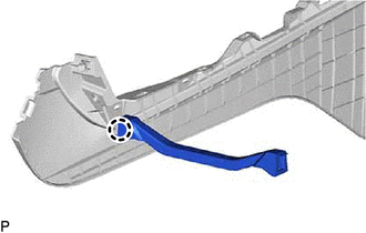
17. REMOVE CONSOLE BOX RETAINER
| (a) Disengage the claw to remove the console box retainer. |
|
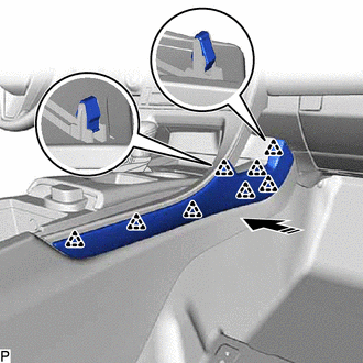
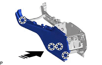
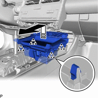
18. REMOVE NO. 1 BOX SIDE PANEL
(a) Disengage the 3 claws as shown in the illustration.
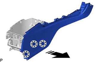
|
|
Remove in this Direction |
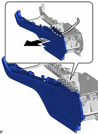
(b)
Using a moulding remover, disengage the 5 claws and 5 guides as shown
in the illustration to remove the No. 1 box side panel.
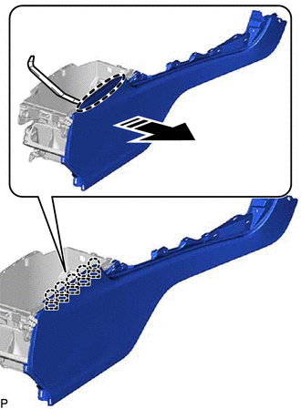
|
|
Insert Moulding Remover Here |
|
|
Remove in this Direction |
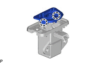
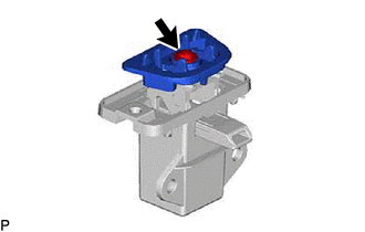
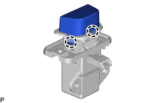
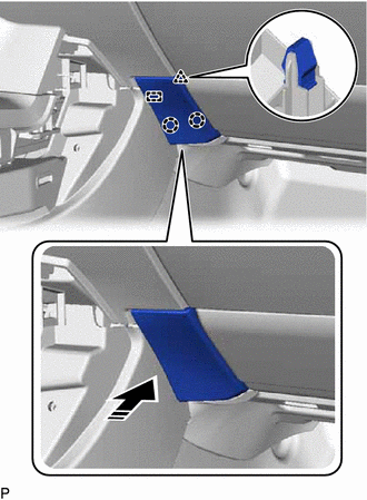
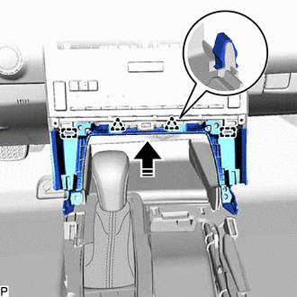
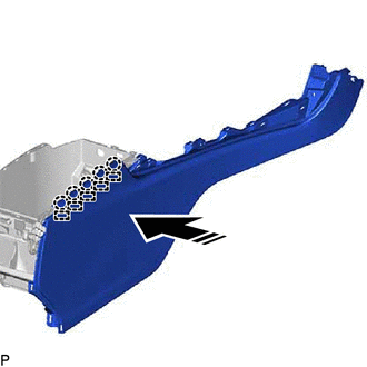
19. REMOVE NO. 2 CONSOLE BOX SUPPORT
(a) Disengage the 2 claws and guide as shown in the illustration to remove the No. 2 console box support.
|
|
Remove in this Direction |
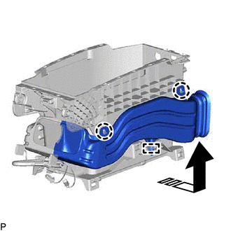
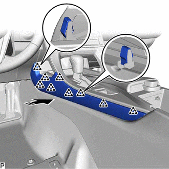
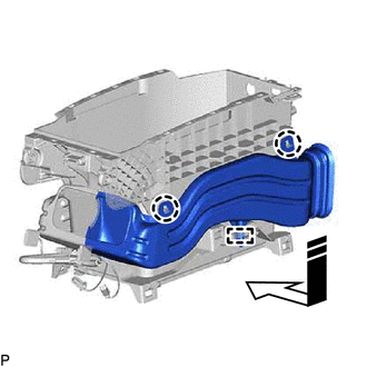
20. REMOVE NO. 3 CONSOLE BOX DUCT
(a) Disengage the 2 claws and guide as shown in the illustration to remove the No. 3 console box duct.

|
|
Remove in this Direction |
21. REMOVE NO. 5 INTERIOR ILLUMINATION LIGHT SUB-ASSEMBLY
Click here
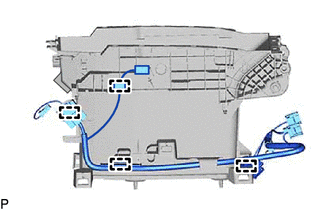
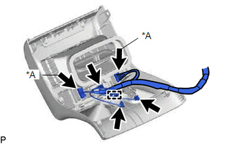
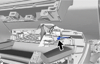
22. REMOVE CONSOLE BOX WIRE
| (a) Disengage the 4 clamps to remove the console box wire. |
|
Installation
INSTALLATION
PROCEDURE
1. INSTALL CONSOLE ASSEMBLY
(a) Engage the 2 clips as shown in the illustration.
 |
Install in this Direction |
(b) Install the console box assembly with the 4 bolts and 2 screws.
(c) Connect the 2 connectors.
2. INSTALL UPPER FRONT CONSOLE PANEL SUB-ASSEMBLY
(a) Engage the clamp and connect the connector.
(b) Engage the 4 clips as shown in the illustration to install the upper front console panel sub-assembly.
|
|
Install in this Direction |
3. INSTALL CONSOLE BOX BEZEL
(a) Connect the connector.
(b) Engage the 6 clips as shown in the illustration to install the console box bezel.
|
|
Install in this Direction |
4. INSTALL INSTRUMENT PANEL FINISH PANEL END LH
(a) Engage the guide, 2 claws and clip as shown in the illustration to install the instrument panel finish panel end LH.
|
|
Install in this Direction |
5. INSTALL REAR UPPER CONSOLE PANEL SUB-ASSEMBLY
(a) Connect the 2 connectors.
(b) Engage the 7 clips as shown in the illustration to install the rear upper console panel sub-assembly.

|
|
Install in this Direction |
6. INSTALL SHIFT LEVER KNOB SUB-ASSEMBLY
for Gasoline Model: Click here 
for HV Model: Click here
7. INSTALL CENTER INSTRUMENT CLUSTER FINISH PANEL SUB-ASSEMBLY
(a) Engage the 2 guides and 2 clips as shown in the illustration.
|
|
Install in this Direction |
(b) Install the center instrument cluster finish panel sub-assembly with the 4 screws.
8. INSTALL CONSOLE BOX POCKET SUB-ASSEMBLY
(a) Engage the 12 clips as shown in the illustration to install the console box pocket sub-assembly.

|
|
Install in this Direction (1) |
 |
Install in this Direction (2) |
9. INSTALL FRONT CONSOLE UPPER PANEL GARNISH
(a) Engage the 2 clamps and connect the 4 connectors.
(b) Engage the 6 clips as shown in the illustration to install the front console upper panel garnish.

|
|
Install in this Direction |
10. INSTALL LOWER INSTRUMENT PANEL FINISH PANEL RH
(a) Engage the 8 clips as shown in the illustration to install the lower instrument panel finish panel RH.
|
|
Install in this Direction |
11. INSTALL LOWER INSTRUMENT PANEL FINISH PANEL LH
(a) Engage the 9 clips as shown in the illustration to install the lower instrument panel finish panel LH.
|
|
Install in this Direction |
12. INSTALL CONSOLE BOX CARPET
(a) Install the console box carpet.
13. INSTALL CONSOLE BOX POCKET
(a) Install the console box pocket.
Reassembly
REASSEMBLY
PROCEDURE
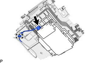
1. INSTALL CONSOLE BOX WIRE
| (a) Engage the 4 clamps to install the console box wire. |
|
2. INSTALL NO. 5 INTERIOR ILLUMINATION LIGHT SUB-ASSEMBLY
Click here

3. INSTALL NO. 3 CONSOLE BOX DUCT
(a) Engage the guide and 2 claws as shown in the illustration to install the No. 3 console box duct.
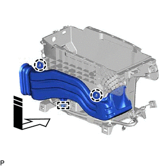
 |
Install in this Direction |
4. INSTALL NO. 2 CONSOLE BOX SUPPORT
(a) Engage the guide and 2 claws as shown in the illustration to install the No. 2 console box support.
|
|
Install in this Direction |
5. INSTALL NO. 1 BOX SIDE PANEL
(a) Engage the 5 guides and 5 claws as shown in the illustration.
|
|
Install in this Direction |
(b) Engage the 3 claws as shown in the illustration to install the No. 1 box side panel.
|
|
Install in this Direction |
6. INSTALL CONSOLE BOX RETAINER
| (a) Engage the claw to install the console box retainer. |
|
7. INSTALL NO. 2 BOX SIDE PANEL
(a) Engage the 5 guides and 5 claws as shown in the illustration.
|
|
Install in this Direction |
(b) Engage the 4 claws as shown in the illustration to install the No. 2 box side panel.
|
|
Install in this Direction |
8. INSTALL STEREO JACK ADAPTER ASSEMBLY
Click here
9. INSTALL USB CHARGER SOCKET (for Front Side)
Click here
10. INSTALL CONSOLE COMPARTMENT DOOR HINGE RETAINER
| (b) Install the console compartment door hinge retainer with the screw. |
|
11. INSTALL UPPER CONSOLE RETAINER
| (a) Engage the 2 claws to install the upper console retainer. |
|
12. INSTALL CONSOLE COMPARTMENT DOOR LOCK SUB-ASSEMBLY
| (b) Install the console compartment door lock sub-assembly with the 2 screws. |
|
13. INSTALL CONSOLE COMPARTMENT DOOR HINGE SUB-ASSEMBLY
| (a) Install the console compartment door hinge sub-assembly with the 8 screws. |
|
14. INSTALL CONSOLE COMPARTMENT DOOR CUSHION
| (a) Engage the 3 clips to install the 3 console compartment door cushions. |
|
15. INSTALL CONSOLE COMPARTMENT DOOR PANEL
| (a) Engage the 14 claws to install the console compartment door panel. |
|
16. INSTALL REAR CONSOLE ARMREST ASSEMBLY
(a) Insert the rear console armrest assembly as shown in the illustration.
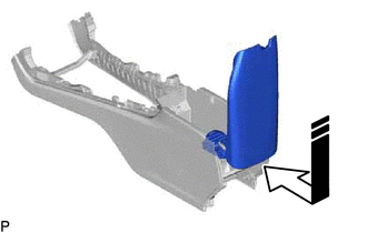
|
|
Install in this Direction |
| (b) Engage the guide to install the console box mount bracket spring and console box spacer. |
|
(c) Install the console compartment door stopper pin as shown in the illustration.
|
|
Install in this Direction |
| (e) Engage the 2 guides to install the rear console armrest assembly. |
|
17. INSTALL CONSOLE BOX REGISTER ASSEMBLY
| (a) Engage the 6 claws to install the console box register assembly. |
|
18. INSTALL SEAT HEATER SWITCH (w/ Seat Heater System)
Click here
19. INSTALL USB CHARGER SOCKET (for Rear Side)
Click here
20. INSTALL CONSOLE BOX ORNAMENT
| (a) Engage the 2 guides and 6 clips to install the console box ornament. |
|
21. INSTALL NO. 6 INTERIOR ILLUMINATION LIGHT SUB-ASSEMBLY
Click here
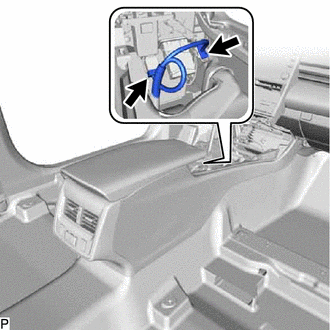
22. INSTALL CONSOLE REAR END PANEL SUB-ASSEMBLY
(b) Connect each connector.
(c) Engage the 4 claws and 4 clips as shown in the illustration to install the console rear end panel sub-assembly.
|
|
Install in this Direction |
Removal
REMOVAL
PROCEDURE
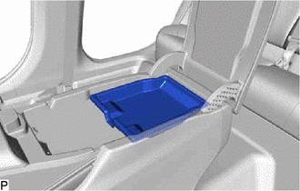
1. REMOVE CONSOLE BOX POCKET
| (a) Remove the console box pocket. | |
2. REMOVE CONSOLE BOX CARPET
| (a) Remove the console box carpet. | |
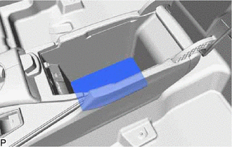
3. REMOVE LOWER INSTRUMENT PANEL FINISH PANEL LH
(a) Disengage the 9 clips as shown in the illustration to remove the lower instrument panel finish panel LH.

 |
Remove in this Direction |
4. REMOVE LOWER INSTRUMENT PANEL FINISH PANEL RH
(a) Disengage the 8 clips as shown in the illustration to remove the lower instrument panel finish panel RH.
|
|
Remove in this Direction |
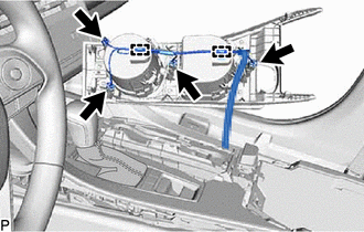
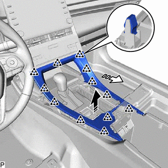
5. REMOVE FRONT CONSOLE UPPER PANEL GARNISH
(a) Disengage the 6 clips as shown in the illustration.
|
|
Remove in this Direction |
| (b) Disconnect the 4 connectors. | |
(c) Disengage the 2 clamps to remove the front console upper panel garnish.
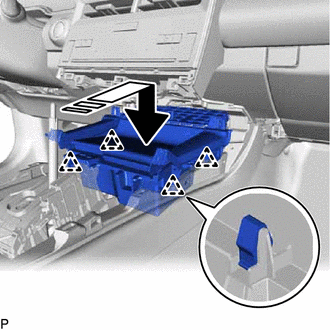
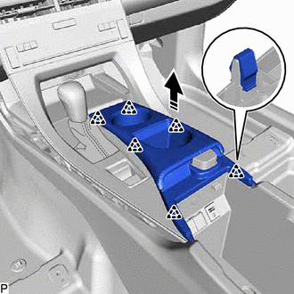
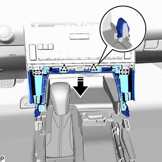
6. REMOVE CONSOLE BOX POCKET SUB-ASSEMBLY
(a) Disengage the 12 clips as shown in the illustration to remove the console box pocket sub-assembly.
|
|
Remove in this Direction (1) |
 |
Remove in this Direction (2) |
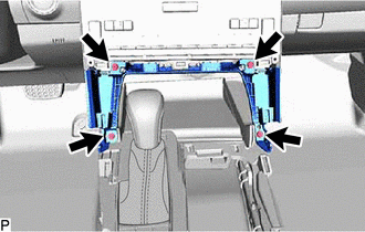
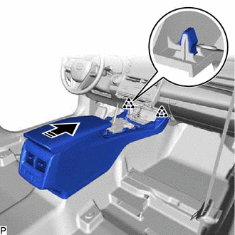
7. REMOVE CENTER INSTRUMENT CLUSTER FINISH PANEL SUB-ASSEMBLY
(b)
Disengage the 2 clips and 2 guides as shown in the illustration to
remove the center instrument cluster finish panel sub-assembly.
|
|
Remove in this Direction |
8. REMOVE SHIFT LEVER KNOB SUB-ASSEMBLY
for Gasoline Model: Click here 
for HV Model: Click here
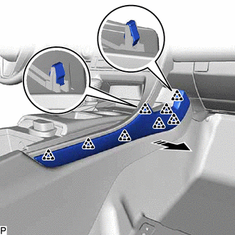
9. REMOVE REAR UPPER CONSOLE PANEL SUB-ASSEMBLY
(a) Disengage the 7 clips as shown in the illustration.
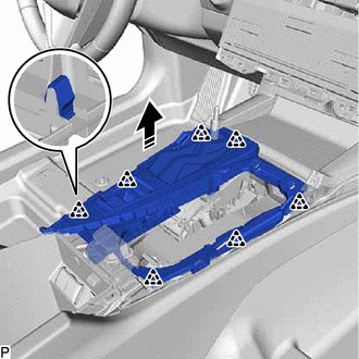
|
|
Remove in this Direction |
| (b) Disconnect the 2 connectors to remove the rear upper console panel sub-assembly. |
|
10. REMOVE INSTRUMENT PANEL FINISH PANEL END LH
(a) Disengage the 2 claws, clip and guide as shown in the illustration to remove the instrument panel finish panel end LH.
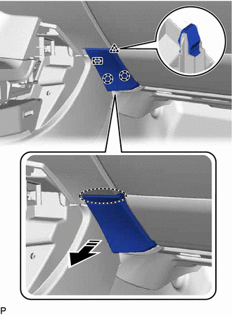
 |
Place Hand Here |
|
|
Remove in this Direction |
11. REMOVE CONSOLE BOX BEZEL
(a) Disengage the 6 clips as shown in the illustration.
|
|
Remove in this Direction |
| (b) Disconnect the connector to remove the console box bezel. |
|
12. REMOVE UPPER FRONT CONSOLE PANEL SUB-ASSEMBLY
(a) Disengage the 4 clips as shown in the illustration.
|
|
Remove in this Direction |
| (b) Disconnect the connector and disengage the clamp to remove the upper front console panel sub-assembly. |
|
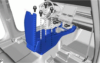
13. REMOVE CONSOLE ASSEMBLY
| (a) Disconnect the 2 connectors. | |
| (b) Remove the 4 bolts and 2 screws. | |
(c) Disengage the 2 clips as shown in the illustration to remove the console assembly.

|
|
Remove in this Direction |