Precaution
PRECAUTION
NOTICE:
When
disconnecting the cable from the negative (-) battery terminal,
initialize the following systems after the cable is reconnected.
|
System Name | See Procedure |
|
Lane Departure Alert System (w/ Steering Control) |
 |
|
Intelligent Clearance Sonar System |
|
Parking Assist Monitor System |
|
Panoramic View Monitor System |
|
Pre-collision System |
|
Lighting System (for Gasoline Model with Cornering Light) |
PRECAUTION FOR DISCONNECTING CABLE FROM NEGATIVE BATTERY TERMINAL
PRECAUTION FOR REPLACING COMBINATION METER ASSEMBLY
When
replacing the combination meter assembly, always replace it with a new
one. If a combination meter assembly which was installed to another
vehicle is used, the information stored in it will not match the
information from the vehicle and a DTC may be stored.
FUEL RECEIVER GAUGE OPERATION
(a) OPERATION
The
combination meter assembly uses the fuel sender gauge assembly to
detect the amount of fuel remaining in the fuel tank assembly. The Hall
IC built into the fuel sender gauge assembly changes the output voltage
according to the amount of fuel remaining. The combination meter
assembly receives fuel injection volume signals from the ECM and detects
the voltage output from the fuel sender gauge assembly and operates the
fuel receiver gauge.
(b) FUEL RECEIVER GAUGE READING
(1) During normal driving:
As
the fuel level in the fuel tank assembly changes when driving on a hill
or applying the brakes, the fuel receiver gauge reading is updated
according to the fuel injection volume during normal driving. However,
as the fuel injection volume measurement has a margin of error, the
value is indicated after correction by input values from the fuel sender
gauge assembly.
(2) During refueling:
The
fuel level in the fuel tank assembly rises rapidly when fuel is added.
If the averaging process that is used during normal driving is used in
this case, the fuel receiver gauge reading cannot be updated promptly.
Therefore, when it is judged that fuel is being added to the vehicle
based on the changes in the fuel level, output values from the fuel
sender gauge assembly is immediately reflected in the fuel receiver
gauge reading. This control is called refueling judgment.
(c) REFUELING JUDGMENT CONDITIONS
NOTICE:
Add
fuel with the engine switch off to ensure safety and to enable
refueling judgment so that an appropriate fuel receiver gauge reading
will be obtained.
(1) Normal judgment condition (When normal refueling method is used)
With
the engine switch off, the fuel sender gauge assembly detects a change
of 5.0 liters (5.3 US qts, 4.4 Imp. qts) or more in the fuel level.
(2) Other judgment conditions (When other refueling method is used)
Any of the following conditions is met:
- With the vehicle and engine stopped and the engine switch on (IG), the
fuel sender gauge assembly detects a change of 5.0 liters (5.3 US qts,
4.4 Imp. qts) or more in the fuel level.
- With the vehicle stopped, the engine switch is on (IG), the fuel sender
gauge assembly detects a change of 15.0 liters (15.9 US qts, 13.2 Imp.
qts) or more in the fuel level.
(d) PRECAUTION FOR REFUELING
(1)
The fuel sender gauge assembly cannot detect changes in the fuel level
within certain ranges (around points E and F). Therefore, even if 5.0
liters (5.3 US qts, 4.4 Imp. qts) or more of fuel is added, refueling
judgment may not be performed and the fuel receiver gauge reading may
not change when fuel level is within such ranges.
(2)
The fuel sender gauge reading takes approximately 25 seconds to rise
from point E to F. If the vehicle is driven while the fuel sender gauge
reading is rising, the fuel sender gauge reading will stop rising. After
the fuel sender gauge reading stops rising, normal fuel sender gauge
reading operation begins. The fuel sender gauge reading takes
approximately 1 minutes per 1 liter (1.1 US qts, 0.9 Imp. qts) to rise
while the vehicle is being driven, and takes approximately 8 minutes per
1 liter (1.1 US qts, 0.9 Imp. qts) to rise while the vehicle is
stopped.
(e) FORCED RESET OF FUEL RECEIVER GAUGE
When
driving at a vehicle speed of 1.8 km/h (1 mph) or more, if the output
value from the fuel sender gauge assembly is different from the fuel
receiver gauge reading by 15.0 liters (15.9 US qts, 13.2 Imp. qts) or
more for approximately 5 minutes, the output value from the fuel sender
gauge assembly is immediately reflected in the fuel receiver gauge
reading to compensate for a situation when refueling judgment cannot be
made.
SERVICE MODE (w/ Toyota Entune Remote Connect)
NOTICE:
- Before servicing, enter service mode to restrain telematics
communication functions and prevent the Toyota Entune Remote Connect
from being operated while servicing.
- Service mode can be entered by using the Techstream or operating the radio and display receiver assembly.
(a) Service mode
HINT:
To cancel service mode, turn the engine switch off and on (IG) to display the service mode screen and cancel service mode.
(1) Service mode (Using the Techstream)
- Connect the Techstream to the DLC3.
- Turn the engine switch on (IG).
- Turn the Techstream on.
- Enter the following menus: Body Electrical / Telematics / Trouble Codes.
Body Electrical > Telematics > Trouble Codes (2) Service mode (When not using the Techstream)
- Start diagnostic mode.
w/o Navigation System: Click here 
w/ Navigation System: Click here 
Speed Signal Circuit
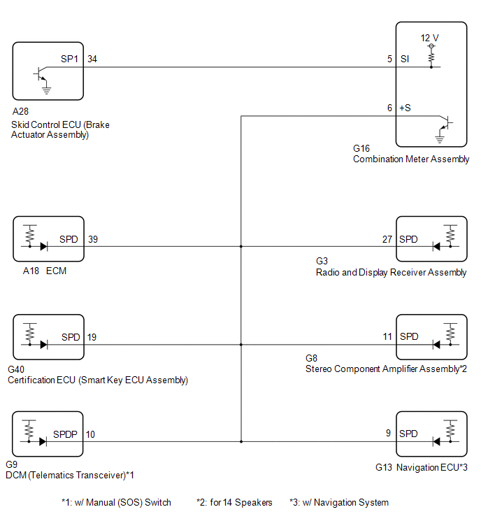
DESCRIPTION
The combination
meter assembly receives the vehicle speed signal from this circuit. The
wheel speed sensors produce an output that varies according to the
vehicle speed. The wheel speed sensor output is received by the skid
control ECU (brake actuator assembly) which uses this information to
create the vehicle speed signal*. The vehicle speed signal consists of
pulses sent to the combination meter assembly from the skid control ECU
(brake actuator assembly). To create this signal, 12 V is output from
IG2 which is behind a resistor in the combination meter assembly. This
voltage is sent to the skid control ECU (brake actuator assembly). The
pulse signal is created by switching the transistor in the skid control
ECU (brake actuator assembly) on and off, making the voltage on the wire
drop to 0 V. A similar system is used for the output of this signal
from the combination meter assembly via terminal +S. A voltage of 12 V
is applied to terminal +S from each ECU or relay that is connected to
this terminal. The transistor in the combination meter assembly is
controlled by the signal from the skid control ECU (brake actuator
assembly). When this transistor is turned on, this transistor makes the
voltage supplied by the various ECUs (via their respective internal
resistors) drop to 0 V. Each ECU connected to terminal +S of the
combination meter assembly controls its respective system based on this
pulse signal.
- *: This vehicle speed signal is created by the skid control ECU (brake
actuator assembly). There is no actual component that is referred to as
the vehicle speed sensor. In addition, for some systems, vehicle speed
information may be received via CAN communication.
HINT:
This
circuit is used for the systems connected to terminal +S. This signal is
not used for combination meter assembly operation. Combination meter
assembly components such as the speedometer operate using data received
via CAN communication.
WIRING DIAGRAM

CAUTION / NOTICE / HINT
NOTICE:
When
replacing the combination meter assembly, always replace it with a new
one. If a combination meter assembly which was installed to another
vehicle is used, the information stored in it will not match the
information from the vehicle and a DTC may be stored.
PROCEDURE
| 1. |
INSPECT COMBINATION METER ASSEMBLY (OUTPUT VOLTAGE) |

|
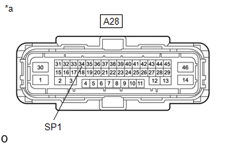
*a | Front view of wire harness connector
(to Skid Control ECU (Brake Actuator Assembly)) |
(a) Disconnect the A28 skid control ECU (brake actuator assembly) connector.
(b) Measure the voltage according to the value(s) in the table below.
Standard Voltage:
|
Tester Connection | Condition |
Specified Condition |
|
A28-34 (SP1) - Body ground |
Engine switch on (IG) |
11 to 14 V |
| NG |
 | GO TO STEP 5 |
|
OK |
 | |
| 2. |
INSPECT SKID CONTROL ECU (BRAKE ACTUATOR ASSEMBLY) (OUTPUT WAVEFORM) |

|
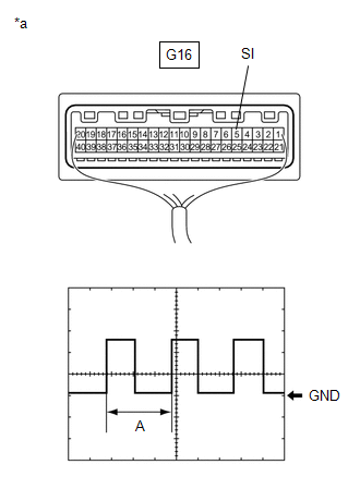
*a | Component with harness connected
(Combination Meter Assembly) |
(a) Connect the A28 skid control ECU (brake actuator assembly) connector.
(b) Remove the combination meter assembly with the connector(s) still connected.
(c) Check the signal waveform according to the condition(s) in the table below.
|
Item | Condition |
|
Tester connection | G16-5 (SI) - Body ground |
|
Tool setting | 5 V/DIV., 20 ms./DIV. |
|
Condition | Engine switch on (IG), wheel being rotated |
OK:
The waveform is similar to that shown in the illustration.
HINT:
When
the system is functioning normally, one wheel revolution generates 4
pulses. As the vehicle speed increases, the width indicated by (A) in
the illustration narrows.
| NG |  |
REPLACE SKID CONTROL ECU (BRAKE ACTUATOR ASSEMBLY) |
|
OK |
 | |
| 3. |
CHECK HARNESS AND CONNECTOR (EACH ECU - COMBINATION METER ASSEMBLY) |
(a) Disconnect the G16 combination meter assembly connector.
(b) Disconnect the A18 ECM connector.
(c) Disconnect the G40 certification ECU (smart key ECU assembly) connector.
(d) Disconnect the G9 DCM (telematics transceiver)*1 connector.
(e) Disconnect the G3 radio and display receiver assembly connector.
(f) Disconnect the G8 stereo component amplifier assembly*2 connector.
(g) Disconnect the G13 navigation ECU*3 connector.
(h) Measure the resistance according to the value(s) in the table below.
Standard Resistance:
|
Tester Connection | Condition |
Specified Condition |
|
A18-39 (SPD) - G16-6 (+S) |
Always | Below 1 Ω |
|
G40-19 (SPD) - G16-6 (+S) |
Always | Below 1 Ω |
|
G9-10 (SPDP)*1 - G16-6 (+S) |
Always | Below 1 Ω |
|
G3-27 (SPD) - G16-6 (+S) |
Always | Below 1 Ω |
|
G8-11 (SPD)*2 - G16-6 (+S) |
Always | Below 1 Ω |
|
G13-9 (SPD)*3 - G16-6 (+S) |
Always | Below 1 Ω |
|
A18-39 (SPD), G40-19 (SPD), G9-10 (SPDP)*1, G3-27 (SPD), G8-11 (SPD)*2, G13-9 (SPD)*3 or G16-6 (+S) - Body ground |
Always | 10 kΩ or higher |
- *1: w/ Manual (SOS) Switch
- *2: for 14 Speakers
- *3: w/ Navigation System
| NG |
 | REPAIR OR REPLACE HARNESS OR CONNECTOR |
|
OK |
 | |
| 4. |
CHECK COMBINATION METER GLASS (OUTPUT WAVEFORM) |

|
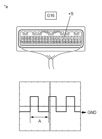
*a | Component with harness connected
(Combination Meter Assembly) |
(a) Connect the G16 combination meter assembly connector.
(b) Connect a positive (+) lead from the battery to any of the following terminals:
- A18-39 (SPD) ECM connector
- G40-19 (SPD) certification ECU (smart key ECU assembly) connector
- G9-10 (SPDP) DCM (telematics transceiver)*1 connector
- G3-27 (SPD) radio and display receiver assembly connector
- G8-11 (SPD) stereo component amplifier assembly*2 connector
- G13-9 (SPD) navigation ECU*3 connector
- *1: w/ Manual (SOS) Switch
- *2: for 14 Speakers
- *3: w/ Navigation System
(c) Check the signal waveform according to the condition(s) in the table below.
|
Item | Condition |
|
Tester connection | G16-6 (+S) - Body ground |
|
Tool setting | 5 V/DIV., 20 ms./DIV. |
|
Condition | Engine switch on (IG), wheel being rotated |
OK:
The waveform is similar to that shown in the illustration.
HINT:
- When the system is functioning normally, one wheel revolution generates 4
pulses. As the vehicle speed increases, the width indicated by (A) in
the illustration narrows.
- If the result is OK, an internal malfunction of a connected ECU can be suspected.
- If the result is NG, an internal malfunction of the combination meter assembly can be suspected.
| OK |
 | REPLACE DEFECTIVE ECU |
| NG |
 | REPLACE COMBINATION METER ASSEMBLY |
| 5. |
CHECK HARNESS AND CONNECTOR (SKID CONTROL ECU (BRAKE ACTUATOR ASSEMBLY) - COMBINATION METER ASSEMBLY) |
(a) Disconnect the G16 combination meter assembly connector.
(b) Measure the resistance according to the value(s) in the table below.
Standard Resistance:
|
Tester Connection | Condition |
Specified Condition |
|
A28-34 (SP1) - G16-5 (SI) |
Always | Below 1 Ω |
|
A28-34 (SP1) or G16-5 (SI) - Body ground |
Always | 10 kΩ or higher |
| OK |
 | REPLACE COMBINATION METER ASSEMBLY |
| NG |
 | REPAIR OR REPLACE HARNESS OR CONNECTOR |


