Toyota Avalon (XX50): Dtc Check / Clear. Engine Coolant Temperature Receiver Gauge Malfunction. Engine Oil Level Sensor Circuit
Dtc Check / Clear
DTC CHECK / CLEAR
CHECK FOR DTC (METER / GAUGE SYSTEM)
(a) Connect the Techstream to the DLC3.
(b) Turn the power switch on (IG).
(c) Turn the Techstream on.
(d) Enter the following menus: Body Electrical / Combination Meter / Trouble Codes.
Body Electrical > Combination Meter > Trouble Codes
(e) Check for DTCs.
CLEAR DTC
(a) Connect the Techstream to the DLC3.
(b) Turn the power switch on (IG).
(c) Turn the Techstream on.
(d) Enter the following menus: Body Electrical / Combination Meter / Clear DTCs.
Body Electrical > Combination Meter > Trouble Codes
(e) Clear the DTCs.
Engine Coolant Temperature Receiver Gauge Malfunction
DESCRIPTION
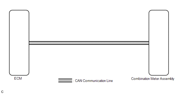
In this
circuit, the combination meter assembly receives engine coolant
temperature signals from the ECM via CAN communication. The combination
meter assembly displays an engine coolant temperature warning based on
the data received from the ECM.
WIRING DIAGRAM

CAUTION / NOTICE / HINT
NOTICE:
- When replacing the combination meter assembly, always replace it with a
new one. If a combination meter assembly which was installed to another
vehicle is used, the information stored in it will not match the
information from the vehicle and a DTC may be stored.
- Before replacing the ECM, refer to Registration.
Click here 
HINT:
If there is an open or short in the engine coolant temperature sensor circuit, the ECM stores DTCs. Troubleshoot the SFI system.
Click here 
PROCEDURE
| 1. |
CHECK CAN COMMUNICATION SYSTEM |
(a) Check if CAN communication system DTCs are output.
Click here 
|
Result | Proceed to |
|
DTCs are not output | A |
|
DTCs are output | B |
| B |
 | GO TO CAN COMMUNICATION SYSTEM |
|
A |
 | |
| 2. |
CHECK FOR DTC (SFI SYSTEM) |
(a) Check if SFI system DTCs are output.
Powertrain > Engine > Trouble Codes
|
Result | Proceed to |
|
DTCs are not output | A |
|
DTCs are output | B |
| B |
 | GO TO SFI SYSTEM |
|
A |
 | |
| 3. |
PERFORM ACTIVE TEST USING TECHSTREAM |

|
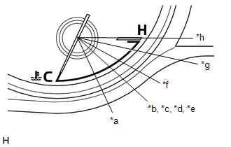
*a | Water Temperature Meter Operation (50C,122F) |
|
*b | Water Temperature Meter Operation (60C,140F) |
|
*c | Water Temperature Meter Operation (70C,158F) |
|
*d | Water Temperature Meter Operation (80C,176F) |
|
*e | Water Temperature Meter Operation (Middle) |
|
*f | Water Temperature Meter Operation (110C,230F) |
|
*g | Water Temperature Meter Operation (120C,248F) |
|
*h | Water Temperature Meter Operation (127C,260F) |
(a) Connect the Techstream to the DLC3.
(b) Turn the power switch on (IG).
(c) Turn the Techstream on.
(d) Enter the following menus: Body Electrical / Combination Meter / Active Test.
(e) Perform the Active Test according to the display on the Techstream.
Body Electrical > Combination Meter > Active Test
|
Tester Display | Measurement Item |
Control Range | Diagnostic Note |
|
Water Temperature Meter Operation (50C,122F) |
Engine coolant temperature receiver gauge (50°C, 122°F) |
ON | - |
|
Water Temperature Meter Operation (60C,140F) |
Engine coolant temperature receiver gauge (60°C, 140°F) |
ON | - |
|
Water Temperature Meter Operation (70C,158F) |
Engine coolant temperature receiver gauge (70°C, 158°F) |
ON | - |
|
Water Temperature Meter Operation (80C,176F) |
Engine coolant temperature receiver gauge (80°C, 176°F) |
ON | - |
|
Water Temperature Meter Operation (Middle) |
Engine coolant temperature receiver gauge (Middle) |
ON | - |
|
Water Temperature Meter Operation (110C,230F) |
Engine coolant temperature receiver gauge (110°C, 230°F) |
ON | - |
|
Water Temperature Meter Operation (120C,248F) |
Engine coolant temperature receiver gauge (120°C, 248°F) |
ON | - |
|
Water Temperature Meter Operation (127C,260F) |
Engine coolant temperature receiver gauge (127°C, 260°F) |
ON | - |
Body Electrical > Combination Meter > Active Test
|
Tester Display |
| Water Temperature Meter Operation (50C,122F) |
Body Electrical > Combination Meter > Active Test
|
Tester Display |
| Water Temperature Meter Operation (60C,140F) |
Body Electrical > Combination Meter > Active Test
|
Tester Display |
| Water Temperature Meter Operation (70C,158F) |
Body Electrical > Combination Meter > Active Test
|
Tester Display |
| Water Temperature Meter Operation (80C,176F) |
Body Electrical > Combination Meter > Active Test
|
Tester Display |
| Water Temperature Meter Operation (Middle) |
Body Electrical > Combination Meter > Active Test
|
Tester Display |
| Water Temperature Meter Operation (110C,230F) |
Body Electrical > Combination Meter > Active Test
|
Tester Display |
| Water Temperature Meter Operation (120C,248F) |
Body Electrical > Combination Meter > Active Test
|
Tester Display |
| Water Temperature Meter Operation (127C,260F) |
OK:
Engine coolant temperature receiver gauge operation is normal.
| OK |
 | REPLACE ECM |
| NG |
 | REPLACE COMBINATION METER ASSEMBLY |
Engine Oil Level Sensor Circuit
DESCRIPTION
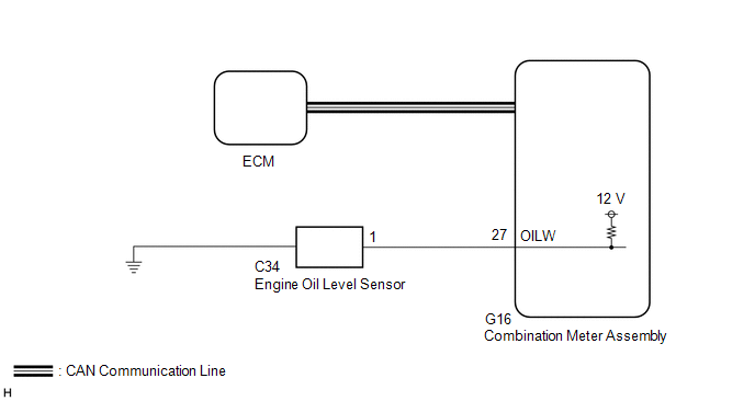
The combination
meter assembly and engine oil level sensor are connected via direct
line. The combination meter assembly determines the engine oil level
based on the engine oil level sensor ON/OFF signal.
HINT:
As
the engine oil level may be unstable when the engine is cold or running
at high speeds, the combination meter assembly receives the engine
coolant temperature signal and engine speed signal from the ECM via CAN
communication in order to prevent the oil level warnings from being
output erroneously.
WIRING DIAGRAM

CAUTION / NOTICE / HINT
NOTICE:
- When replacing the combination meter assembly, always replace it with a
new one. If a combination meter assembly which was installed to another
vehicle is used, the information stored in it will not match the
information from the vehicle and a DTC may be stored.
- The following troubleshooting procedure is based on the assumption that
the SFI system is normal. Confirm that the SFI system is not
malfunctioning before performing the following procedure.
Click here 
PROCEDURE
|
1. | INSPECT ENGINE OIL LEVEL SENSOR |
(a) Remove the engine oil level sensor.
Click here

(b) Inspect the engine oil level sensor.
Click here 
| NG |
 | REPLACE ENGINE OIL LEVEL SENSOR |
|
OK |
 | |
| 2. |
CHECK HARNESS AND CONNECTOR (ENGINE OIL LEVEL SENSOR - COMBINATION METER ASSEMBLY) |
(a) Disconnect the G16 combination meter assembly connector.
(b) Measure the resistance according to the value(s) in the table below.
Standard Resistance:
|
Tester Connection | Condition |
Specified Condition |
|
C34-1 - G16-27 (OILW) |
Always | Below 1 Ω |
|
C34-1 or G16-27 (OILW) - Body ground |
Always | 10 kΩ or higher |
| OK |
 | REPLACE COMBINATION METER ASSEMBLY |
| NG |
 | REPAIR OR REPLACE HARNESS OR CONNECTOR |


