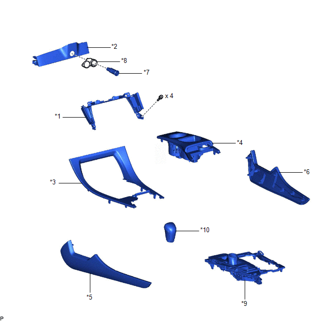
Installation
INSTALLATION
PROCEDURE
1. INSTALL NO. 1 POWER OUTLET SOCKET COVER
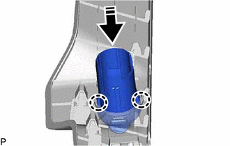
(a) Engage the 2 claws to install the No. 1 power outlet socket cover as shown in the illustration.
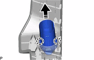
 | Install in this Direction |
2. INSTALL NO. 1 POWER OUTLET SOCKET ASSEMBLY
(a) Engage the claw to install the No. 1 power outlet socket assembly as shown in the illustration.
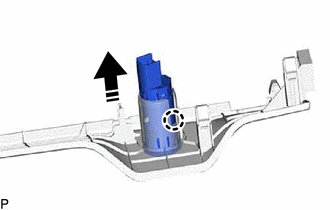
 | Install in this Direction |
3. INSTALL CONSOLE BOX BEZEL
Click here

4. INSTALL REAR UPPER CONSOLE PANEL SUB-ASSEMBLY
Click here 
5. INSTALL SHIFT LEVER KNOB SUB-ASSEMBLY
Click here 
6. INSTALL CENTER INSTRUMENT CLUSTER FINISH PANEL SUB-ASSEMBLY
Click here 
7. INSTALL CONSOLE BOX POCKET SUB-ASSEMBLY
Click here 
8. INSTALL FRONT CONSOLE UPPER PANEL GARNISH
Click here 
9. INSTALL LOWER INSTRUMENT PANEL FINISH PANEL RH
Click here 
10. INSTALL LOWER INSTRUMENT PANEL FINISH PANEL LH
Click here 
Removal
REMOVAL
PROCEDURE
1. REMOVE LOWER INSTRUMENT PANEL FINISH PANEL LH
Click here 
2. REMOVE LOWER INSTRUMENT PANEL FINISH PANEL RH
Click here 
3. REMOVE FRONT CONSOLE UPPER PANEL GARNISH
Click here 
4. REMOVE CONSOLE BOX POCKET SUB-ASSEMBLY
Click here 
5. REMOVE CENTER INSTRUMENT CLUSTER FINISH PANEL SUB-ASSEMBLY
Click here 
6. REMOVE SHIFT LEVER KNOB SUB-ASSEMBLY
Click here 
7. REMOVE REAR UPPER CONSOLE PANEL SUB-ASSEMBLY
Click here 
8. REMOVE CONSOLE BOX BEZEL
Click here 
9. REMOVE NO. 1 POWER OUTLET SOCKET ASSEMBLY
(a)
Using a screwdriver with its tip wrapped with protective tape,
disengage the claw and remove the No. 1 power outlet socket assembly as
shown in the illustration.
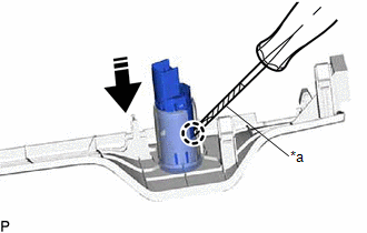
|
*a | Protective Tape |
 |
Remove in this Direction |
10. REMOVE NO. 1 POWER OUTLET SOCKET COVER
(a) Disengage the 2 claws and remove the No. 1 power outlet socket cover as shown in the illustration.
 | Remove in this Direction |
