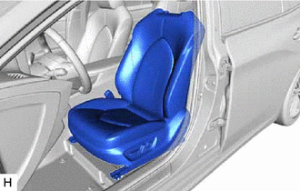
Components
COMPONENTS
ILLUSTRATION
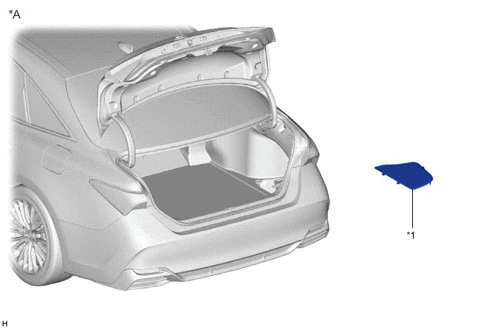
|
*A | for HV Model |
- | - |
|
*1 | LUGGAGE TRIM SERVICE HOLE COVER |
- | - |
ILLUSTRATION
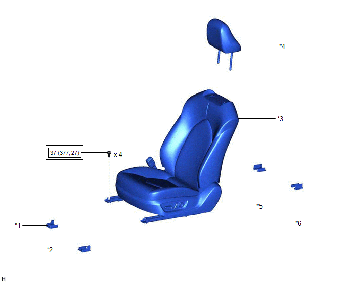
|
*1 | FRONT INNER SEAT TRACK BRACKET COVER |
*2 | FRONT OUTER SEAT TRACK BRACKET COVER |
|
*3 | FRONT SEAT ASSEMBLY |
*4 | FRONT SEAT HEADREST ASSEMBLY |
|
*5 | REAR INNER SEAT TRACK BRACKET COVER |
*6 | REAR OUTER SEAT TRACK BRACKET COVER |
 |
Tightening torque for "Major areas involving basic vehicle performance such as moving/turning/stopping": N*m (kgf*cm, ft.*lbf) |
- | - |
ILLUSTRATION
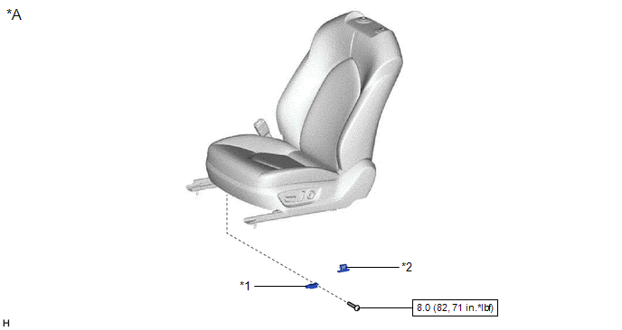
|
*A | for Driver Side |
- | - |
|
*1 | SEAT POSITION AIRBAG SENSOR |
*2 | SEAT SLIDE POSITION SENSOR PROTECTOR |
 |
N*m (kgf*cm, ft.*lbf): Specified torque |
- | - |
ILLUSTRATION
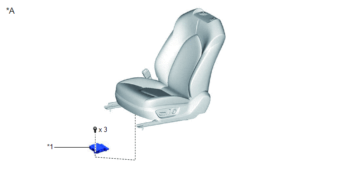
|
*A | w/ Seat Position Memory System |
- | - |
|
*1 | POSITION CONTROL ECU ASSEMBLY LH |
- | - |
ILLUSTRATION
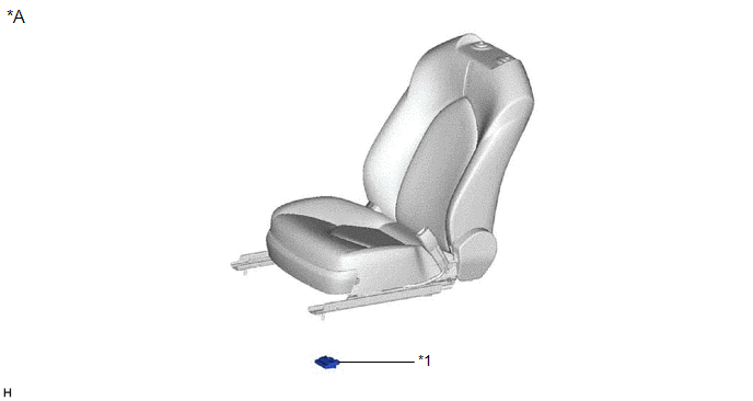
|
*A | for Front Passenger Side |
- | - |
|
*1 | OCCUPANT DETECTION ECU |
- | - |
ILLUSTRATION
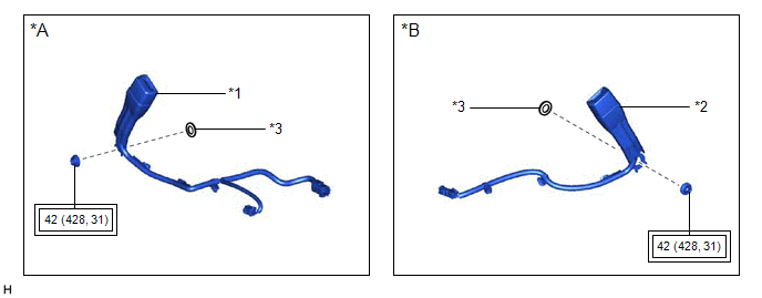
|
*A | for Driver Side |
*B | for Front Passenger Side |
|
*1 | FRONT SEAT INNER BELT ASSEMBLY LH |
*2 | FRONT SEAT INNER BELT ASSEMBLY RH |
|
*3 | FRONT SEAT BELT ANCHOR PLATE |
- | - |
 |
Tightening torque for "Major areas involving basic vehicle performance such as moving/turning/stopping": N*m (kgf*cm, ft.*lbf) |
- | - |
ILLUSTRATION
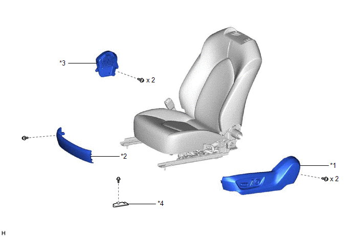
|
*1 | FRONT SEAT CUSHION SHIELD |
*2 | FRONT SEAT FRONT CUSHION SHIELD |
|
*3 | FRONT SEAT INNER CUSHION SHIELD |
*4 | FRONT SEAT LOWER CUSHION SHIELD |
ILLUSTRATION
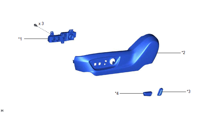
|
*1 | FRONT POWER SEAT SWITCH |
*2 | FRONT SEAT CUSHION SHIELD |
|
*3 | RECLINING POWER SEAT SWITCH KNOB |
*4 | SLIDE AND VERTICAL POWER SEAT SWITCH KNOB |
ILLUSTRATION
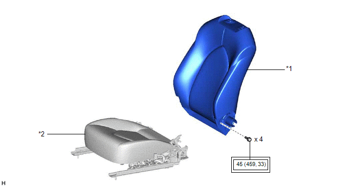
|
*1 | SEPARATE TYPE FRONT SEATBACK ASSEMBLY |
*2 | SEPARATE TYPE FRONT SEAT CUSHION ASSEMBLY |
 |
Tightening torque for "Major areas involving basic vehicle performance such as moving/turning/stopping": N*m (kgf*cm, ft.*lbf) |
- | - |
ILLUSTRATION
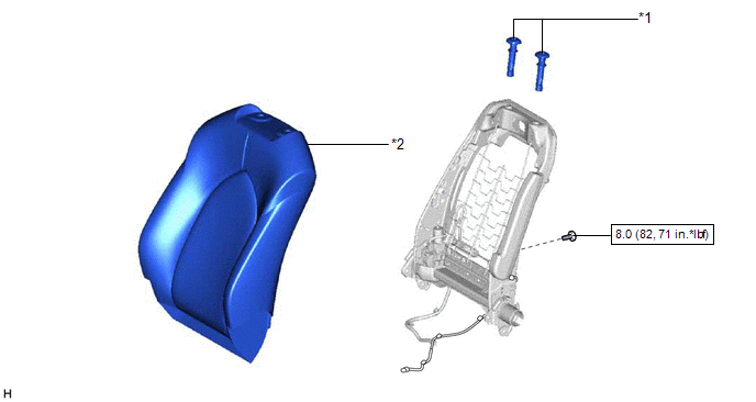
|
*1 | FRONT SEAT HEADREST SUPPORT |
*2 | SEPARATE TYPE FRONT SEATBACK COVER WITH PAD |
 |
N*m (kgf*cm, ft.*lbf): Specified torque |
- | - |
ILLUSTRATION
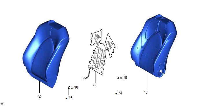
|
*1 | FRONT SEATBACK HEATER ASSEMBLY |
*2 | SEPARATE TYPE FRONT SEATBACK COVER |
|
*3 | SEPARATE TYPE FRONT SEATBACK PAD |
*4 | TAG PIN |
|
*5 | HOG RING |
- | - |
|
â—Ź | Non-reusable part |
- | - |
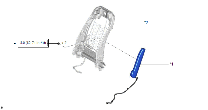
ILLUSTRATION
|
*1 | FRONT SEAT AIRBAG ASSEMBLY |
*2 | SEPARATE TYPE FRONT SEATBACK SPRING ASSEMBLY |
 |
Tightening torque for "Major areas involving basic vehicle performance such as moving/turning/stopping": N*m (kgf*cm, ft.*lbf) |
â—Ź | Non-reusable part |
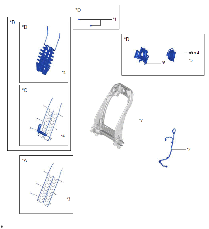
ILLUSTRATION
|
*A | w/o Lumbar Support |
*B | w/ Lumbar Support |
|
*C | w/o Climate Control Seat System |
*D | w/ Climate Control Seat System |
|
*1 | FRONT NO. 2 SEATBACK HOOK |
*2 | FRONT SEAT NO. 2 WIRE |
|
*3 | FRONT SEATBACK SPRING SUB-ASSEMBLY RH |
*4 | LUMBAR SUPPORT ADJUSTER ASSEMBLY |
|
*5 | SEATBACK CLIMATE CONTROL BLOWER |
*6 | SEATBACK BLOWER FAN ADAPTER |
|
*7 | FRONT SEATBACK FRAME SUB-ASSEMBLY |
- | - |
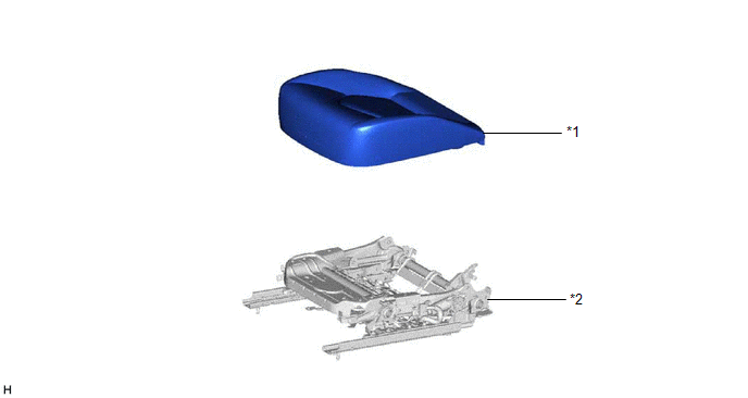
ILLUSTRATION
|
*1 | SEPARATE TYPE FRONT SEAT CUSHION COVER WITH PAD |
*2 | SEPARATE TYPE FRONT SEAT CUSHION SPRING ASSEMBLY |
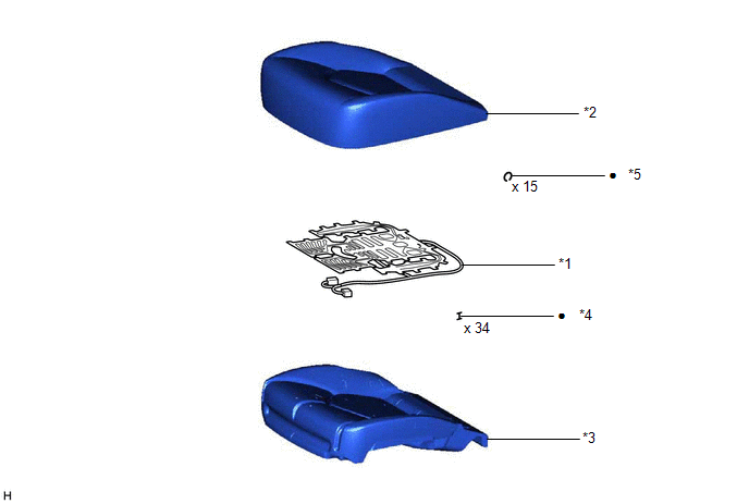
ILLUSTRATION
|
*1 | FRONT SEAT CUSHION HEATER ASSEMBLY |
*2 | SEPARATE TYPE FRONT SEAT CUSHION COVER |
|
*3 | SEPARATE TYPE FRONT SEAT CUSHION PAD |
*4 | TAG PIN |
|
*5 | HOG RING |
- | - |
|
â—Ź | Non-reusable part |
- | - |
ILLUSTRATION
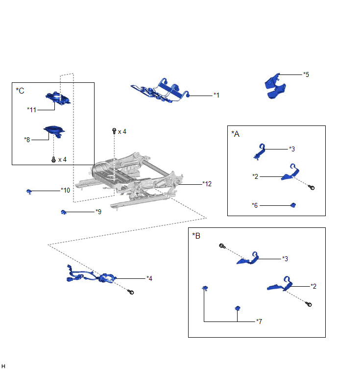
|
*A | for Driver Side |
*B | for Front Passenger Side |
|
*C | w/ Climate Control Seat System |
- | - |
|
*1 | FRONT SEAT CUSHION SPRING SUB-ASSEMBLY |
*2 | FRONT SEAT LOWER CUSHION SHIELD LH |
|
*3 | FRONT SEAT LOWER CUSHION SHIELD RH |
*4 | FRONT SEAT WIRE |
|
*5 | LH SEAT RECLINING ADJUSTER INSIDE COVER |
*6 | LH SEAT SEAT TRACK UPPER RAIL COVER |
|
*7 | RH SEAT SEAT TRACK UPPER RAIL COVER |
*8 | SEAT CUSHION CLIMATE CONTROL BLOWER |
|
*9 | SEAT TRACK UPPER RAIL COVER LH |
*10 | SEAT TRACK UPPER RAIL COVER RH |
|
*11 | SEAT CUSHION BLOWER FAN ADAPTER |
*12 | FRONT SEAT ADJUSTER ASSEMBLY |
Disassembly
DISASSEMBLY
CAUTION / NOTICE / HINT
CAUTION:
Wear protective gloves. Sharp areas on the parts may injure your hands.
HINT:
- Use the same procedure for the RH side and LH side.
- The following procedure is for the LH side.
PROCEDURE
1. REMOVE SEAT POSITION AIRBAG SENSOR (for Driver Side)
Click here 
2. REMOVE POSITION CONTROL ECU ASSEMBLY LH (w/ Seat Position Memory System)
Click here 
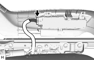
3. REMOVE OCCUPANT DETECTION ECU (for Front Passenger Side)
Click here 
4. REMOVE FRONT SEAT INNER BELT ASSEMBLY LH (for Driver Side)
Click here 
5. REMOVE FRONT SEAT INNER BELT ASSEMBLY RH (for Front Passenger Side)
Click here 
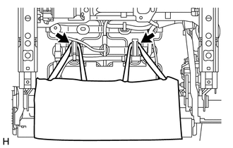
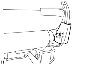
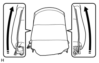
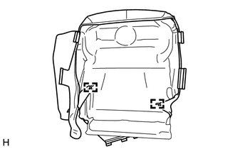
6. DISCONNECT SEPARATE TYPE FRONT SEATBACK COVER
| (a) Disconnect the 2 rubber bands of the separate type front seatback cover. |
|
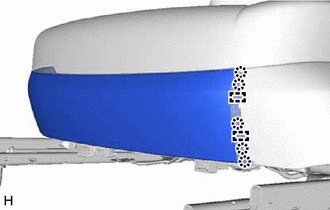
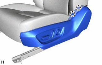
7. REMOVE FRONT SEAT FRONT CUSHION SHIELD
| (b) Disengage the 5 claws and 2 guides to remove the front seat front cushion shield. |
|
8. REMOVE FRONT SEAT CUSHION SHIELD
| (b) Disengage the 2 claws. | |
(c)
Using a screwdriver with its tip wrapped with protective tape,
disengage the 2 claws and slightly pull the front seat cushion shield as
shown in the illustration.
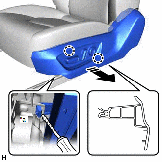
|
*a | Protective Tape |
 |
Remove in this Direction |
(d) Disengage the guide as shown in the illustration.
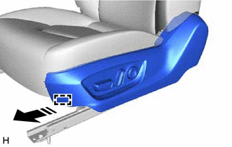
 |
Remove in this Direction |
| (e) Disconnect the front power seat switch connector to remove the front seat cushion shield. |
|
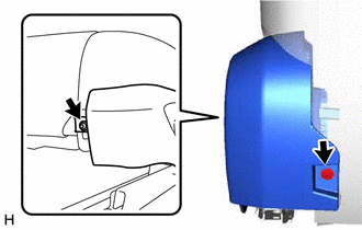
9. REMOVE FRONT SEAT INNER CUSHION SHIELD
(b) Disengage the guide to remove the front seat inner cushion shield as shown in the illustration.
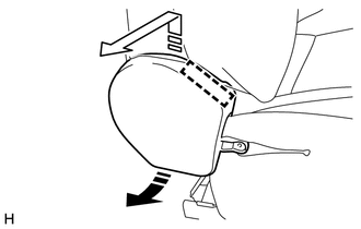
 |
Remove in this Direction (1) |
 |
Remove in this Direction (2) |
10. REMOVE FRONT SEAT LOWER CUSHION SHIELD
(b) Disengage the claw to remove the front seat lower cushion shield as shown in the illustration.
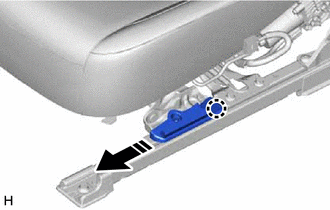
 |
Remove in this Direction |
11. REMOVE SLIDE AND VERTICAL POWER SEAT SWITCH KNOB
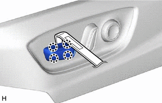
| (a) Using a moulding remover, disengage the 4 claws to remove the slide and vertical power seat switch knob. |
|
12. REMOVE RECLINING POWER SEAT SWITCH KNOB
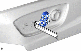
| (a) Using a moulding remover, disengage the 4 claws to remove the reclining power seat switch knob. |
|
13. REMOVE FRONT POWER SEAT SWITCH
Click here

14. REMOVE SEPARATE TYPE FRONT SEATBACK ASSEMBLY
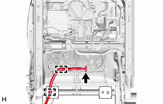
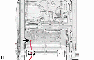
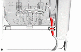
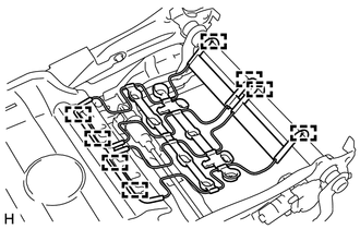
| (b) Disengage the claw and 3 clamps to separate the front seat airbag assembly wire harness.
HINT: Disengage the 3 clamps first. | |
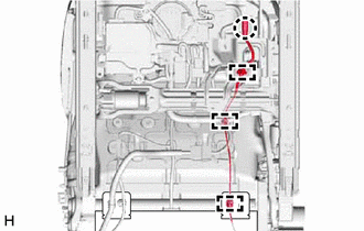
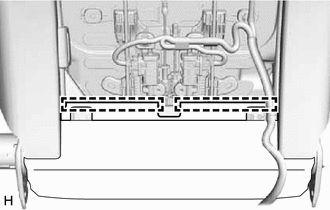
| (c) Disengage the 2 clamps. | |
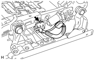
(d) Disconnect the connector to separate the front seat No. 2 wire.
(f) Disconnect the connector to separate the front seatback heater assembly connector.
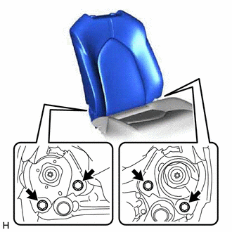
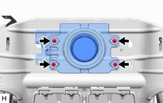
| (g) Remove the 4 bolts to remove the separate type front seatback assembly from the separate type front seat cushion assembly. |
|
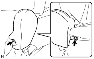
15. REMOVE FRONT SEAT HEADREST SUPPORT
| (a) Open the 2 fasteners. | |
| (c) Disengage the 2 hooks. | |
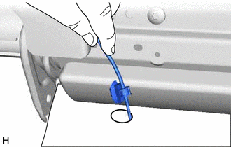
| (d) Pass each wire harness through the hole of the separate type front seatback cover. |
|
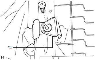
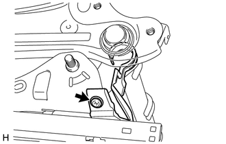
| (e) Using a T25 "TORX" socket wrench, remove the screw and disengage the 2 brackets. |
|
| (f)
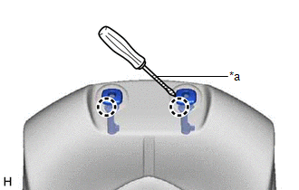
Using a screwdriver with its tip wrapped with protective tape,
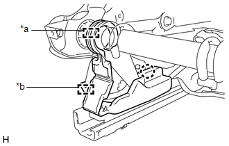
disengage the 2 claws and remove the 2 front seat headrest supports. |
|
16. REMOVE SEPARATE TYPE FRONT SEATBACK COVER WITH PAD
(a) Remove the separate type front seatback cover with pad.
17. REMOVE SEPARATE TYPE FRONT SEATBACK COVER
(a)
Remove the 10 hog rings, disengage the fastener and remove the separate
type front seatback cover from the separate type front seatback pad.
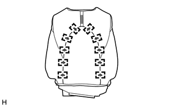
 |
Fastener |
18. REMOVE FRONT SEATBACK HEATER ASSEMBLY
Click here 
19. REMOVE FRONT SEAT AIRBAG ASSEMBLY
Click here 
20. REMOVE SEATBACK CLIMATE CONTROL BLOWER (w/ Climate Control Seat System)
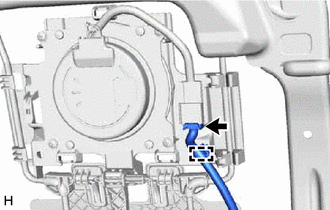
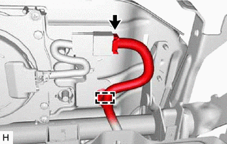
| (a) Disengage the wire harness clamp and disconnect the connector.
HINT: Disengage the wire harness clamp first. | |
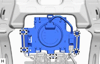
| (b) Disengage the 2 claws and 3 hooks. HINT: Disengage the 2 claws first. |
|
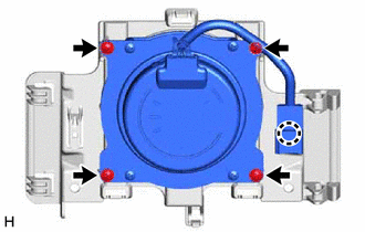
(d) Remove the 4 screws and seatback climate control blower from the seatback blower fan adapter.
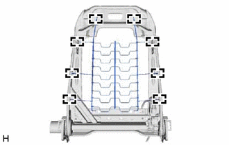
21. REMOVE FRONT SEATBACK SPRING SUB-ASSEMBLY RH (w/o Lumbar Support)
| (a) Disengage the 8 hooks to remove the front seatback spring sub-assembly RH from the front seatback frame sub-assembly. |
|
22. REMOVE LUMBAR SUPPORT ADJUSTER ASSEMBLY (w/ Lumbar Support)
Click here

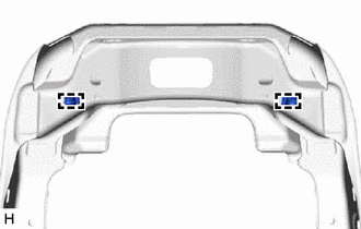
23. REMOVE FRONT NO. 2 SEATBACK HOOK (w/ Climate Control Seat System)
| (a) Disengage the 2 clamps to remove the 2 front No. 2 seatback hooks from the front seatback frame sub-assembly. |
|
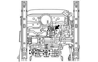
24. REMOVE FRONT SEAT NO. 2 WIRE
(a) Disconnect each connector and disengage each clamp to remove the front seat No. 2 wire.
25. REMOVE SEPARATE TYPE FRONT SEAT CUSHION COVER WITH PAD
| (a) Disengage the 4 clamps. | |
(b) Disconnect the connector to separate the front seat cushion heater assembly wire harness.
(c)
Disengage the 9 hooks and remove the separate type front seat cushion
cover with pad from the separate type front seat cushion spring
assembly.
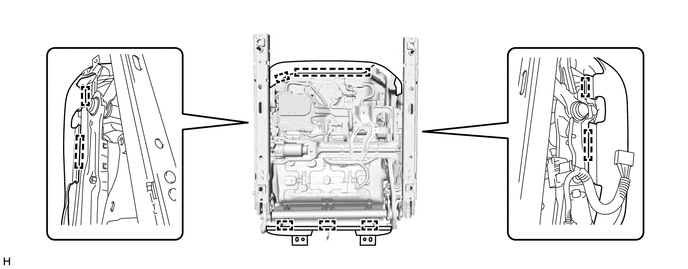
26. REMOVE SEPARATE TYPE FRONT SEAT CUSHION COVER
| (a) Remove the 2 hog rings. | |
(b)
Remove the 13 hog rings, disengage the 2 fasteners and remove the
separate type front seat cushion cover from the separate type front seat
cushion pad.
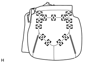
 |
Fastener |
27. REMOVE FRONT SEAT CUSHION HEATER ASSEMBLY
Click here 
28. REMOVE LH SEAT RECLINING ADJUSTER INSIDE COVER
| (a) Disengage the 2 guides to remove the LH seat reclining adjuster inside cover. |
|
29. REMOVE FRONT SEAT LOWER CUSHION SHIELD LH (for Driver Side)
(b) Disengage the hook.
|
(c) Disengage the claw and guide to remove the front seat lower cushion shield LH. |
|
30. REMOVE FRONT SEAT LOWER CUSHION SHIELD RH (for Driver Side)
(b) Disengage the 2 claws to remove the front seat lower cushion shield RH.
31. REMOVE FRONT SEAT LOWER CUSHION SHIELD LH (for Front Passenger Side)
(c) Disengage the claw and guide to remove the front seat lower cushion shield LH.
32. REMOVE FRONT SEAT LOWER CUSHION SHIELD RH (for Front Passenger Side)
HINT:
Use the same procedure as for the front seat lower cushion shield LH (for Driver Side).
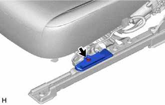
33. REMOVE SEAT TRACK UPPER RAIL COVER LH
(a) Disengage the 2 claws to remove the seat track upper rail cover LH as shown in the illustration.
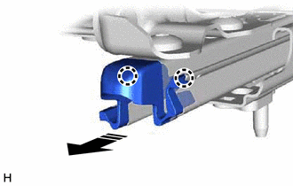
 |
Remove in this Direction |
34. REMOVE SEAT TRACK UPPER RAIL COVER RH
HINT:
Use the same procedure as for the LH side.
35. REMOVE LH SEAT SEAT TRACK UPPER RAIL COVER (for Driver Side)
(a) Disengage the 2 claws to remove the LH seat seat track upper rail cover as shown in the illustration.
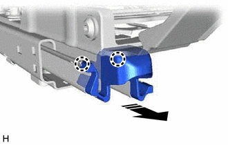
 |
Remove in this Direction |
36. REMOVE RH SEAT SEAT TRACK UPPER RAIL COVER (for Front Passenger Side)
HINT:
- Use the same procedure as for the LH seat seat track upper rail cover (for Driver Side).
- Use the same procedure for both RH seat seat track upper rail covers.
37. REMOVE SEAT CUSHION CLIMATE CONTROL BLOWER (w/ Climate Control Seat System)
| (a) Disengage the wire harness clamp and disconnect the connector. |
|
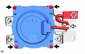
 |
Wire Harness Clamp |
(c) Disengage the claw and wire harness clamp.
HINT:
Disengage the claw first.
(d) Remove the 4 screws and seat cushion climate control blower from the seat cushion blower fan adapter.
38. REMOVE FRONT SEAT WIRE
(b) Disconnect each connector and disengage each clamp to remove the front seat wire.
39. REMOVE FRONT SEAT CUSHION SPRING SUB-ASSEMBLY
| (a) Disengage the 8 hooks to remove the front seat cushion spring sub-assembly from the front seat adjuster assembly. |
|
Inspection
INSPECTION
PROCEDURE
1. INSPECT FRONT SEAT ADJUSTER ASSEMBLY LH
| (a) Check the operation of the slide motor. (1) Check that the seat cushion moves smoothly when the auxiliary battery is connected to the slide motor connector terminals.
OK: |
Auxiliary Battery Connection |
Operational Direction | | Auxiliary battery positive (+) → Terminal 4
Auxiliary battery negative (-) → Terminal 3 |
Seat cushion moves forward | | Auxiliary battery positive (+) → Terminal 3
Auxiliary battery negative (-) → Terminal 4 |
Seat cushion moves backward | If the result is not as specified, replace the front seat adjuster assembly LH. |
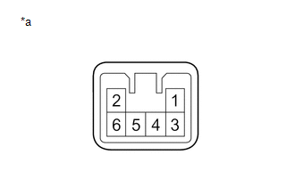 |
|
*a | Component without harness connected
(Slide Motor (Front Seat Adjuster Assembly LH)) | | |
| (b) Check the operation of the front vertical motor. (1)
Check that the seat cushion moves smoothly when the auxiliary battery
is connected to the front vertical motor connector terminals. OK: |
Auxiliary Battery Connection |
Operational Direction | | Auxiliary battery positive (+) → Terminal 3
Auxiliary battery negative (-) → Terminal 1 |
Seat cushion moves upward | |
Auxiliary battery positive (+) → Terminal 1 Auxiliary battery negative (-) → Terminal 3 |
Seat cushion moves downward | If the result is not as specified, replace the front seat adjuster assembly LH. |
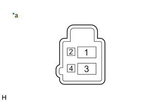 |
|
*a | Component without harness connected
(Front Vertical Motor (Front Seat Adjuster Assembly LH)) | | |
| (c) Check the operation of the lifter motor. (1) Check that the seat cushion moves smoothly when the auxiliary battery is connected to the lifter motor connector terminals.
OK: |
Auxiliary Battery Connection |
Operational Direction | | Auxiliary battery positive (+) → Terminal 3
Auxiliary battery negative (-) → Terminal 1 |
Seat cushion moves upward | |
Auxiliary battery positive (+) → Terminal 1 Auxiliary battery negative (-) → Terminal 3 |
Seat cushion moves downward | If the result is not as specified, replace the front seat adjuster assembly LH. |
 |
|
*a | Component without harness connected
(Lifter Motor (Front Seat Adjuster Assembly LH)) | | |
2. INSPECT FRONT SEATBACK FRAME SUB-ASSEMBLY LH
| (a) Check the operation of the reclining motor. (1) Check that the seatback moves smoothly when the auxiliary battery is connected to the reclining motor connector terminals.
OK: |
Auxiliary Battery Connection |
Operational Direction | | Auxiliary battery positive (+) → Terminal 3
Auxiliary battery negative (-) → Terminal 1 |
Seatback moves forward | |
Auxiliary battery positive (+) → Terminal 1 Auxiliary battery negative (-) → Terminal 3 |
Seatback moves backward | If the result is not as specified, replace the front seatback frame sub-assembly LH. |
 |
|
*a | Component without harness connected
(Reclining Motor (Front Seatback Frame Sub-assembly LH)) | | |
3. INSPECT FRONT SEAT ADJUSTER ASSEMBLY RH
| (a) Check the operation of the slide motor. (1) Check that the seat cushion moves smoothly when the auxiliary battery is connected to the slide motor connector terminals.
OK: |
Auxiliary Battery Connection |
Operational Direction | | Auxiliary battery positive (+) → Terminal 3
Auxiliary battery negative (-) → Terminal 4 |
Seat cushion moves forward | | Auxiliary battery positive (+) → Terminal 4
Auxiliary battery negative (-) → Terminal 3 |
Seat cushion moves backward | If the result is not as specified, replace the front seat adjuster assembly RH. |
 |
|
*a | Component without harness connected
(Slide Motor (Front Seat Adjuster Assembly RH)) | | |
| (b) Check the operation of the front vertical motor. (1)
Check that the seat cushion moves smoothly when the auxiliary battery
is connected to the front vertical motor connector terminals. OK: |
Auxiliary Battery Connection |
Operational Direction | | Auxiliary battery positive (+) → Terminal 1
Auxiliary battery negative (-) → Terminal 3 |
Seat cushion moves upward | |
Auxiliary battery positive (+) → Terminal 3 Auxiliary battery negative (-) → Terminal 1 |
Seat cushion moves downward | If the result is not as specified, replace the front seat adjuster assembly RH. |
 |
|
*a | Component without harness connected
(Front Vertical Motor (Front Seat Adjuster Assembly RH)) | | |
| (c) Check the operation of the lifter motor. (1) Check that the seat cushion moves smoothly when the auxiliary battery is connected to the lifter motor connector terminals.
OK: |
Auxiliary Battery Connection |
Operational Direction | | Auxiliary battery positive (+) → Terminal 3
Auxiliary battery negative (-) → Terminal 1 |
Seat cushion moves upward | |
Auxiliary battery positive (+) → Terminal 1 Auxiliary battery negative (-) → Terminal 3 |
Seat cushion moves downward | If the result is not as specified, replace the front seat adjuster assembly RH. |
 |
|
*a | Component without harness connected
(Lifter Motor (Front Seat Adjuster Assembly RH)) | | |
4. INSPECT FRONT SEATBACK FRAME SUB-ASSEMBLY RH
| (a) Check the operation of the reclining motor. (1) Check that the seatback moves smoothly when the auxiliary battery is connected to the reclining motor connector terminals.
OK: |
Auxiliary Battery Connection |
Operational Direction | | Auxiliary battery positive (+) → Terminal 3
Auxiliary battery negative (-) → Terminal 1 |
Seatback moves forward | |
Auxiliary battery positive (+) → Terminal 1 Auxiliary battery negative (-) → Terminal 3 |
Seatback moves backward | If the result is not as specified, replace the front seatback frame sub-assembly RH. |
 |
|
*a | Component without harness connected
(Reclining Motor (Front Seatback Frame Sub-assembly RH)) | | |
Installation
INSTALLATION
CAUTION / NOTICE / HINT
CAUTION:
Wear protective gloves. Sharp areas on the parts may injure your hands.
HINT:
- Use the same procedure for the RH side and LH side.
- The following procedure is for the LH side.
PROCEDURE
1. INSTALL FRONT SEAT ASSEMBLY
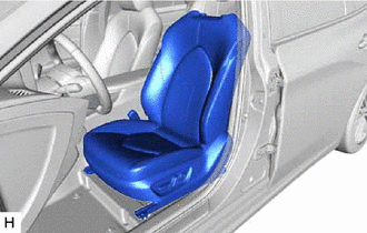
| (a) Place the front seat assembly in the cabin. NOTICE:
Be careful not to damage the vehicle body. | |
(b) Connect the front seat airbag assembly connector under the front seat assembly.
(1) Before connecting the connector, check that the position of the housing lock is correct as shown in the illustration.
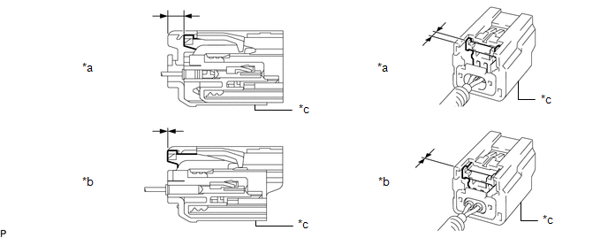
|
*a | Correct |
*b | Incorrect |
|
*c | Yellow CPA |
- | - |
(2) Be sure to engage the connectors until they are locked (when locking, make sure that a click sound can be heard).
NOTICE:
- When connecting any airbag connector, take care not to damage the airbag wire harness.
- When engaged, the white housing lock will slide. Be sure not to hold the
white housing lock and upper part of the yellow CPA, as it may result
in an insecure connection.
(c) Connect each connector and engage each clamp under the front seat assembly.
(d) Connect the cable to the negative (-) auxiliary battery terminal.
for Gasoline Model: Click here

for HV Model: Click here

NOTICE:
When disconnecting the cable, some systems need to be initialized after the cable is reconnected.
Click here 
(e) Temporarily install the front seat assembly with the 4 bolts.
(f) Operate the slide and vertical power seat switch knob and move the front seat assembly to the rearmost position.
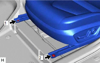
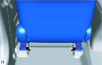
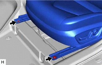
| (g) Using a T50 "TORX" socket wrench, tighten the 2 bolts on the front side of the front seat assembly.
Torque: 37 N·m {377 kgf·cm, 27 ft·lbf} NOTICE: Tighten the bolts in the order shown in the illustration. |
|
(h) Operate the slide and vertical power seat switch knob and move the front seat assembly to the foremost position.
| (i) Using a T50 "TORX" socket wrench, tighten the 2 bolts on the rear side of the front seat assembly.
Torque: 37 N·m {377 kgf·cm, 27 ft·lbf} NOTICE: Tighten the bolts in the order shown in the illustration. |
|
2. INSTALL REAR OUTER SEAT TRACK BRACKET COVER
(a) Engage the claw and guide to install the rear outer seat track bracket cover as shown in the illustration.
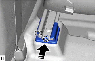
 |
Install in this Direction |
3. INSTALL REAR INNER SEAT TRACK BRACKET COVER
(a) Engage the claw and guide to install the rear inner seat track bracket cover as shown in the illustration.
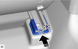
 |
Install in this Direction |
4. INSTALL FRONT OUTER SEAT TRACK BRACKET COVER
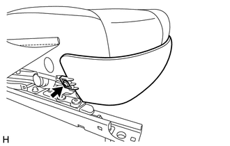
(a) Operate the slide and vertical power seat switch knob and move the front seat assembly to the rearmost position.
(b) Engage the claw and guide to install the front outer seat track bracket cover as shown in the illustration.
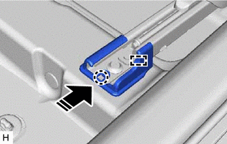
 |
Install in this Direction |
5. INSTALL FRONT INNER SEAT TRACK BRACKET COVER
(a) Engage the claw and guide to install the front inner seat track bracket cover as shown in the illustration.
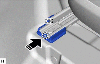
 |
Install in this Direction |
6. INSTALL FRONT SEAT HEADREST ASSEMBLY
(a) Install the front seat headrest assembly to the front seat assembly.
7. INSTALL LUGGAGE TRIM SERVICE HOLE COVER (for HV Model)
Click here

8. INSPECT FRONT SEAT ASSEMBLY
w/o Seat Position Memory System: Click here

for Gasoline Model with Seat Position Memory System: Click here

for HV Model with Seat Position Memory System: Click here

9. CHECK SEAT HEATER
for Gasoline Model: Click here

for HV Model: Click here

10. PERFORM DIAGNOSTIC SYSTEM CHECK
for Gasoline Model: Click here 
for HV Model: Click here

11. INITIALIZATION OF SEAT ECU (w/ Seat Position Memory System)
for Gasoline Model: Click here 
for HV Model: Click here

12. INSPECT CLIMATE CONTROL SEAT SYSTEM (w/ Climate Control Seat System)
for Gasoline Model: Click here 
for HV Model: Click here

13. PERFORM ZERO POINT CALIBRATION AND SENSITIVITY CHECK (for Front Passenger Side)
for Gasoline Model: Click here 
for HV Model: Click here

Precaution
PRECAUTION
HINT:
- The following procedures are used to prevent wrinkles from forming when
installing the seat cover. Make sure to follow the procedures correctly.
- The shape of the seat shown in the illustration may differ from the actual seat.
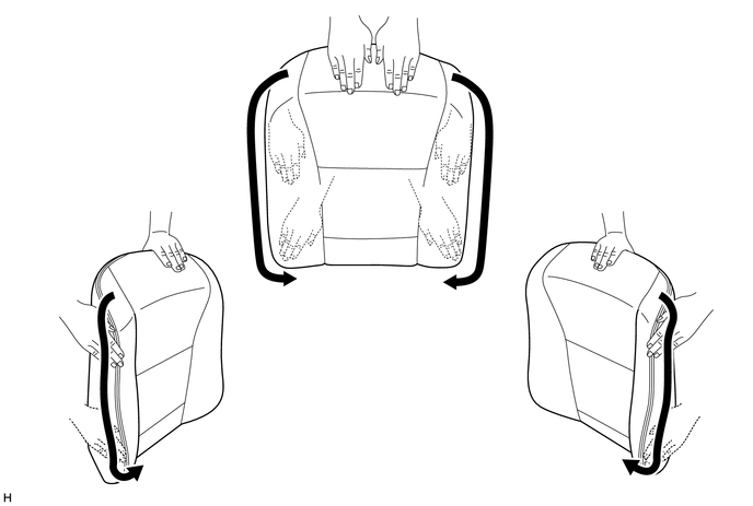
SEAT COVER SET
(a) Align the center cutout of the pad with the V-point of the cover.
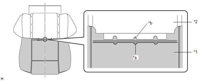
|
*1 | Pad |
*2 | Cover |
|
*a | Center Cutout of Pad |
*b | Cover V-point |
INSTALL HOG RING
(a) Using hog ring pliers, bend the hog rings into the shape shown in the illustration.
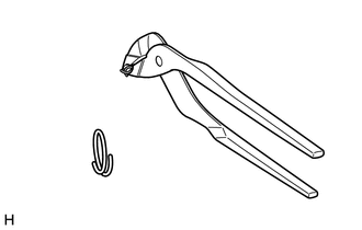
HINT:
Make sure to bend the hog rings into the proper shape. Wrinkles will form if improperly shaped hog rings are used.
(b) Install the hog rings in the order of the wires shown in the illustration.
HINT:
- Install in the following order: Center of seatback, side closest to vehicle exterior, and then side closest to vehicle interior.
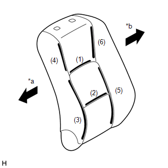
|
*a | Vehicle Exterior |
|
*b | Vehicle Interior |
- Install in the following order: Center of seat cushion, side closest to
vehicle exterior, and then side closest to vehicle interior.

|
*a |
Vehicle Exterior |
|
*b |
Vehicle Interior |
- Install the hog ring so that it is centered in the cutout of the pad.
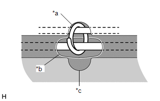
|
*a |
Cover Hole |
|
*b |
Pad Groove |
|
*c |
Pad Cutout |
(c)
After installing the hog rings, hold the seam allowance on both ends of
the cover and pull to match the pad and cover installation areas.
HINT:
If the cover is not matched to the pad, wrinkles will form.
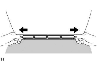
(d) Push the cover seam allowance securely into the groove in the pad.
HINT:
Make
sure to completely push the seam allowance into the groove. Wrinkles
will form if any of the seam allowance is outside the groove.

|
*a | Cover Seam Allowance |
*b | Pad Groove |
|
*c | Correct |
*d | Incorrect |
INSTALL WEBBING (w/ Airbag)
(a) Pass the webbing through the pad hole, and then stretch the webbing so there are no wrinkles.
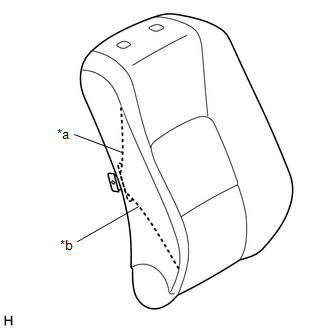
|
*a | Cover Webbing |
|
*b | Pad Hole |
NOTICE:
If there are wrinkles in the webbing, wrinkles will appear on the surface of the cover.
CHECK COVER POSITION
(a)
Fold the cover back as shown in the illustration and check that the
cover V-points and the pad mark-off lines are approximately aligned.
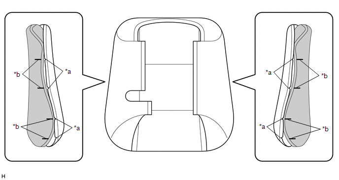
|
*a | Cover V-point |
*b | Pad Mark-off Line |
INSTALL COVER
(a)
Align the cover of the seatback with the center of the seatback pad and
the cover of the seat cushion with the center of the seat cushion pad.
Afterward, install the covers starting from the vehicle exterior and
working toward the vehicle interior.
(b) While
removing wrinkles by hand as shown in the illustration, install the
seatback cover by starting from the bottom and working toward the
shoulders, and then install the seat cushion cover by starting from the
front and working toward the rear.
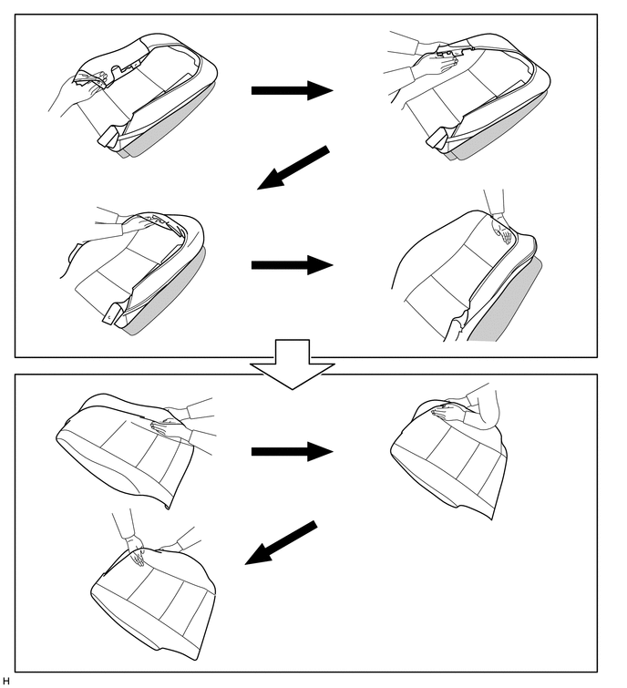
HINT:
- Do not push the pad into the cover. Instead, secure the pad and install the cover to the pad.
- Do not apply an excessive amount of force when covering the corners, as doing so may cause the cover to tear or fray.
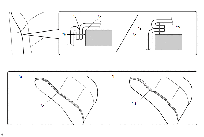
(c) Align the cover seam line with the edges of the pad.
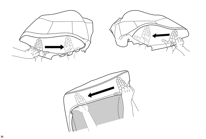
HINT:
- Double-stitch type:

|
*a |
Cover Seam Line |
*b |
Cover Seam (Stitch) |
|
*c |
Pad Edge |
*d |
Felt |
|
*e |
Correct |
*f |
Incorrect |
(d) Push the cover seam allowance securely into the groove in the pad.
HINT:
Make
sure to completely push the seam allowance into the groove. Wrinkles
will form if any of the seam allowance is outside the groove.

REMOVE WRINKLES
(a)
After installing the cover with pad to the seat frame, use your fingers
to trace the seam line of each part and remove wrinkles.
NOTICE:
If there are wrinkles in the webbing, wrinkles will appear on the surface of the cover.
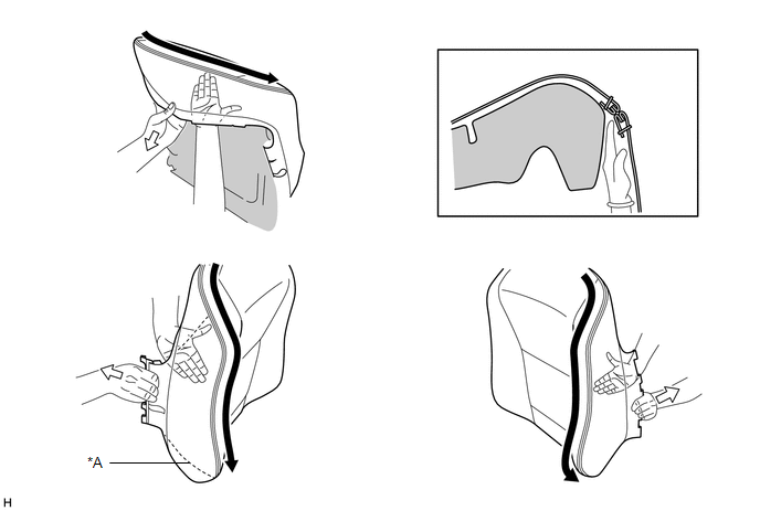
CHECKS TO PERFORM AFTER WORK IS FINISHED
(a) Smooth the cover as shown in the illustration and make sure that there are no wrinkles.
HINT:
- If wrinkles remain, it is very likely that the covering was not properly performed.
- If waves form in the seam line, it is very likely that the seam
allowance is not in the groove or the position of the felt is incorrect.
Removal
REMOVAL
CAUTION / NOTICE / HINT
The
necessary procedures (adjustment, calibration, initialization, or
registration) that must be performed after parts are removed and
installed, or replaced during front seat assembly removal/installation
are shown below.
Necessary Procedures After Parts Removed/Installed/Replaced (for Gasoline Model) |
Replaced Part or Performed Procedure |
Necessary Procedure | Effect/Inoperative Function when Necessary Procedure not Performed |
Link |
|
*: When performing learning using the Techstream.
Click here  |
|
Disconnect cable from negative auxiliary battery terminal |
Perform steering sensor zero point calibration |
Lane departure alert system (w/ Steering Control) |
 |
|
Pre-collision system |
|
Intelligent clearance sonar system* |
|
Lighting system (for Gasoline Model with Cornering Light) |
|
Memorize steering angle neutral point |
Parking assist monitor system |
 |
|
Panoramic view monitor system |
 |
- Occupant detection ECU
- Front passenger seat
| Zero point calibration (Occupant classification system) |
- Occupant classification system
- Passenger airbag ON/OFF indicator
- Airbag system (Front passenger side)
- Seat belt warning system (Front passenger)
|
 |
- Separate type front seat cushion spring assembly LH
- Front seatback frame sub-assembly LH
- Position control ECU assembly
| Initialize position control ECU |
Front power seat control system |
 |
Necessary Procedures After Parts Removed/Installed/Replaced (for HV Model) |
Replaced Part or Performed Procedure |
Necessary Procedure | Effect/Inoperative Function when Necessary Procedure not Performed |
Link |
|
*: When performing learning using the Techstream.
Click here  |
|
Disconnect cable from negative auxiliary battery terminal |
Perform steering sensor zero point calibration |
Lane departure alert system (w/ Steering Control) |
 |
|
Pre-collision system |
|
Intelligent clearance sonar system* |
|
Lighting system (for HV Model with Cornering Light) |
|
Memorize steering angle neutral point |
Parking assist monitor system |
 |
|
Panoramic view monitor system |
 |
- Occupant detection ECU
- Front passenger seat
| Zero point calibration (Occupant classification system) |
- Occupant classification system
- Passenger airbag ON/OFF indicator
- Airbag system (Front passenger side)
- Seat belt warning system (Front passenger)
|
 |
- Separate type front seat cushion spring assembly LH
- Front seatback frame sub-assembly LH
- Position control ECU assembly
| Initialize position control ECU |
Front Power Seat Control System |
 |
CAUTION:
NOTICE:
If the
front seat airbag assembly has been deployed, replace the front seat
airbag assembly, front seatback frame sub-assembly, separate type front
seatback pad and separate type front seatback cover with the necessary
parts in accordance with the extent of the collision damage.
HINT:
- Use the same procedure for the RH side and LH side.
- The following procedure is for the LH side.
PROCEDURE
1. PRECAUTION
NOTICE:
After
turning the engine switch (for Gasoline Model) or power switch (for HV
Model) off, waiting time may be required before disconnecting the cable
from the negative (-) auxiliary battery terminal. Therefore, make sure
to read the disconnecting the cable from the negative (-) auxiliary
battery terminal notices before proceeding with work.
Click here

2. REMOVE LUGGAGE TRIM SERVICE HOLE COVER (for HV Model)
Click here 
3. REMOVE FRONT SEAT HEADREST ASSEMBLY
(a) Remove the front seat headrest assembly from the front seat assembly.
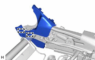
4. REMOVE FRONT OUTER SEAT TRACK BRACKET COVER
(a) Operate the slide and vertical power seat switch knob and move the front seat assembly to the rearmost position.
(b) Disengage the claw and guide to remove the front outer seat track bracket cover as shown in the illustration.
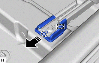
 |
Remove in this Direction |
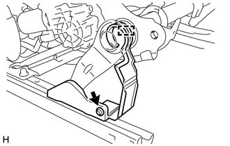
5. REMOVE FRONT INNER SEAT TRACK BRACKET COVER
(a) Disengage the claw and guide to remove the front inner seat track bracket cover as shown in the illustration.
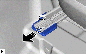
 |
Remove in this Direction |
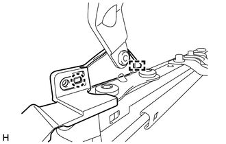
6. REMOVE REAR OUTER SEAT TRACK BRACKET COVER
(a) Operate the slide and vertical power seat switch knob and move the front seat assembly to the foremost position.
(b) Disengage the claw and guide to remove the rear outer seat track bracket cover as shown in the illustration.
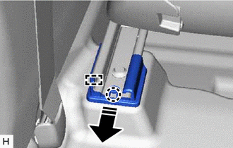
 |
Remove in this Direction |
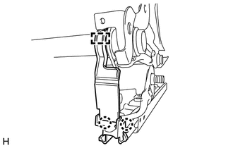
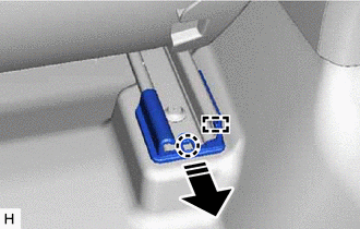
7. REMOVE REAR INNER SEAT TRACK BRACKET COVER
(a) Disengage the claw and guide to remove the rear inner seat track bracket cover as shown in the illustration.
 |
Remove in this Direction |
8. REMOVE FRONT SEAT ASSEMBLY
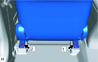
| (a) Using a T50 "TORX" socket wrench, remove the 2 bolts on the rear side of the front seat assembly. |
|
(b) Operate the slide and vertical power seat switch knob and move the front seat assembly to the rearmost position.
| (c) Using a T50 "TORX" socket wrench, remove the 2 bolts on the front side of the front seat assembly. |
|
(d) Operate the reclining power seat switch knob and move the seatback to the upright position.
(e) Operate the slide and vertical power seat switch knob and move the front seat assembly to the center position.
(f) Operate the slide and vertical power seat switch knob and move the front seat assembly to the uppermost position.
(g) Disconnect the cable from the negative (-) auxiliary battery terminal.
for Gasoline Model: Click here 
for HV Model: Click here

CAUTION:
Wait
at least 90 seconds after disconnecting the cable from the negative (-)
auxiliary battery terminal to disable the SRS system.
NOTICE:
When disconnecting the cable, some systems need to be initialized after the cable is reconnected.
Click here 
(h) Disconnect the front seat airbag assembly connector under the front seat assembly.
NOTICE:
When disconnecting any airbag connector, take care not to damage the airbag wire harness.
(1) Push down the white housing lock and slide the yellow CPA. (At this time, the connector cannot be disconnected yet.)
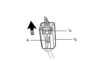
|
*a | White Housing Lock |
|
*b | Yellow CPA |
 |
Slide |
(2) Push down the white housing lock again and disconnect the connector.
NOTICE:
Do not push down the part (A) shown in the illustration when disconnecting the connector.
(i) Disconnect each connector and disengage each clamp under the front seat assembly.
| (j) Remove the front seat assembly. NOTICE: Be careful not to damage the vehicle body. |
|


