Toyota Avalon (XX50): Power Seat Control Ecu
Components
COMPONENTS
ILLUSTRATION
|
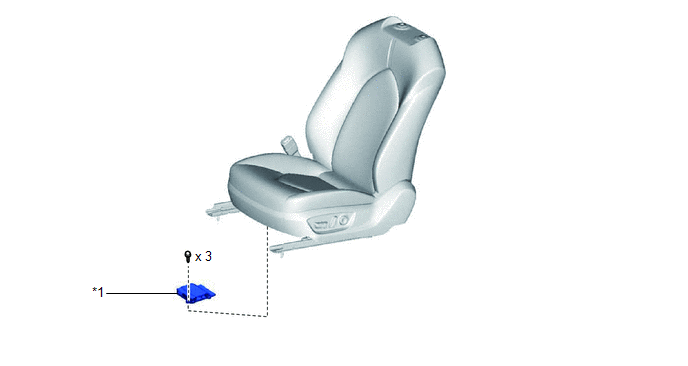
*1 | POSITION CONTROL ECU ASSEMBLY LH |
- | - |
Installation
INSTALLATION
CAUTION / NOTICE / HINT
CAUTION:
Wear protective gloves. Sharp areas on the parts may injure your hands.
PROCEDURE
1. INSTALL POSITION CONTROL ECU ASSEMBLY LH
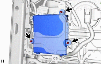
| (a) Install the position control ECU assembly LH with the 3 screws. |
|
| (b) Connect the 3 connectors. | |
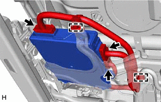
(c) Engage the 2 clamps.
2. INSTALL FRONT SEAT ASSEMBLY LH
Click here

Removal
REMOVAL
CAUTION / NOTICE / HINT
The
necessary procedures (adjustment, calibration, initialization or
registration) that must be performed after parts are removed and
installed, or replaced during position control ECU assembly LH
removal/installation are shown below.
Necessary Procedures After Parts Removed/Installed/Replaced (for Gasoline Model) |
Replaced Part or Performed Procedure |
Necessary Procedure | Effect/Inoperative Function when Necessary Procedure not Performed |
Link |
|
*: When performing learning using the Techstream.
Click here  |
|
Disconnect cable from negative auxiliary battery terminal |
Perform steering sensor zero point calibration |
Lane departure alert system (w/ Steering Control) |
|
|
Pre-collision system |
|
Intelligent clearance sonar system* |
|
Lighting system (for Gasoline Model with Cornering Light) |
|
Memorize steering angle neutral point |
Parking assist monitor system |
|
|
Panoramic view monitor system |
|
- Separate type front seat cushion spring assembly LH
- Front seatback frame sub-assembly LH
- Position control ECU assembly
| Initialize position control ECU |
Front power seat control system |
|
Necessary Procedures After Parts Removed/Installed/Replaced (for HV Model) |
Replaced Part or Performed Procedure |
Necessary Procedure | Effect/Inoperative Function when Necessary Procedure not Performed |
Link |
|
*: When performing learning using the Techstream.
Click here |
|
Disconnect cable from negative auxiliary battery terminal |
Perform steering sensor zero point calibration |
Lane departure alert system (w/ Steering Control) |
|
|
Pre-collision system |
|
Intelligent clearance sonar system* |
|
Lighting system (for HV Model with Cornering Light) |
|
Memorize steering angle neutral point |
Parking assist monitor system |
|
|
Panoramic view monitor system |
|
- Separate type front seat cushion spring assembly LH
- Front seatback frame sub-assembly LH
- Position control ECU assembly
| Initialize position control ECU |
Front power seat control system |
|
CAUTION:
PROCEDURE
1. REMOVE FRONT SEAT ASSEMBLY LH
Click here
2. REMOVE POSITION CONTROL ECU ASSEMBLY LH
| (a) Disengage the 2 clamps. | |
(b) Disconnect the 3 connectors.
| (c) Remove the 3 screws and position control ECU assembly LH. |
|