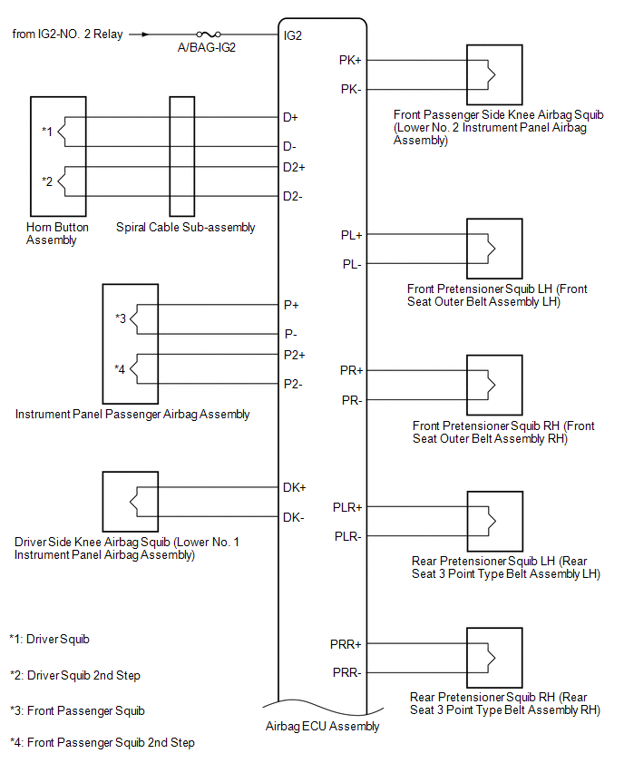
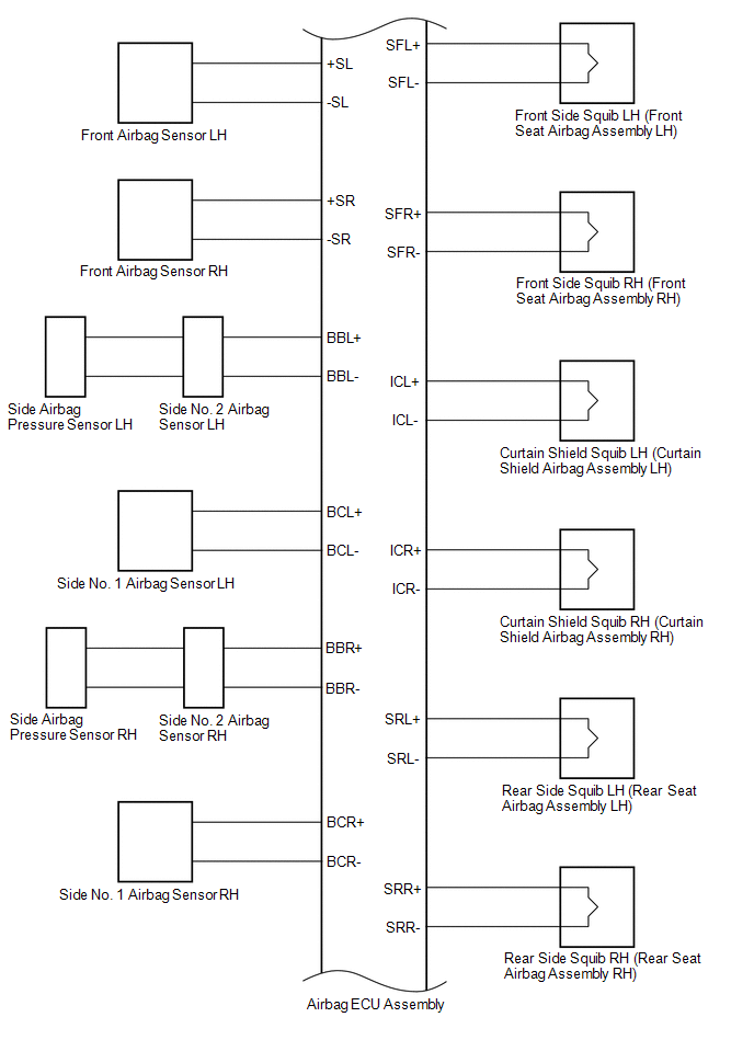
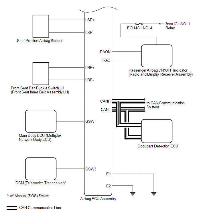
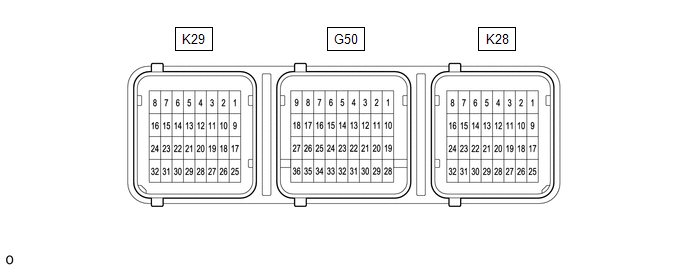
SYSTEM DIAGRAM Transmitting ECU (Transmitter) Receiving ECU Signal Communication Method Airbag ECU Assembly Occupant Detection ECU CAN Airbag ECU Assembly ECM Airbag ECU Assembly Combination Meter Assembly Occupant Detection ECU Airbag ECU Assembly TERMINALS OF ECU AIRBAG ECU ASSEMBLY Terminal No. Terminal Symbol Destination K29-3 PLR- Rear pretensioner squib LH (Rear seat 3 point type belt assembly LH) K29-4 PLR+ K29-5 PL+ Front pretensioner squib LH (Front seat outer belt assembly LH) K29-6 PL- K29-7 ICL- Curtain shield squib LH (Curtain shield airbag assembly LH) K29-8 ICL+ K29-13 SRL+ Rear side squib LH (Rear seat airbag assembly LH) K29-14 SRL- K29-15 SFL- Front side squib LH (Front seat airbag assembly LH) K29-16 SFL+ K29-25 LSP+ Seat position airbag sensor K29-26 LSP- K29-27 LBE- Front seat belt buckle switch LH (Front seat inner belt assembly LH) K29-28 LBE+ K29-29 BCL+ Side No. 1 airbag sensor LH K29-30 BCL- K29-31 BBL- Side No. 2 airbag sensor LH K29-32 BBL+ G50-1 P2+ Front passenger squib 2nd step (Instrument panel passenger airbag assembly) G50-2 P2- G50-3 P- Front passenger squib (Instrument panel passenger airbag assembly) G50-4 P+ G50-6 D+ Driver squib (Horn button assembly) G50-7 D- G50-8 D2- Driver squib 2nd step (Horn button assembly) G50-9 D2+ G50-10 PK+ Front passenger side knee airbag squib (Lower No. 2 instrument panel airbag assembly) G50-11 PK- G50-12 DK- Driver side knee airbag squib (Lower No. 1 instrument panel airbag assembly) G50-13 DK+ G50-23* GSW3 DCM (Telematics transceiver) G50-25 GSW Main body ECU (Multiplex network body ECU) G50-26 CANH CAN communication line G50-27 CANL G50-28 -SR Front airbag sensor RH G50-29 +SR G50-30 +SL Front airbag sensor LH G50-31 -SL G50-32 E2 Ground G50-33 E1 G50-34 P-AB Passenger airbag ON/OFF indicator (Radio and display receiver assembly) G50-35 PAON G50-36 IG2 A/BAG-IG2 fuse K28-1 ICR+ Curtain shield squib RH (Curtain shield airbag assembly RH) K28-2 ICR- K28-3 PR- Front pretensioner squib RH (Front seat outer belt assembly RH) K28-4 PR+ K28-5 PRR+ Rear pretensioner squib RH (Rear seat 3 point type belt assembly RH) K28-6 PRR- K28-9 SFR+ Front side squib RH (Front seat airbag assembly RH) K28-10 SFR- K28-11 SRR- Rear side squib RH (Rear seat airbag assembly RH) K28-12 SRR+ K28-25 BBR+ Side No. 2 airbag sensor RH K28-26 BBR- K28-27 BCR- Side No. 1 airbag sensor RH K28-28 BCR+ DESCRIPTION The airbag ECU assembly sends/receives signals to/from each ECU via CAN communication. DTC No. Detection Item DTC Detection Condition Trouble Area Warning Indicate Test Mode / Check Mode U0154 Lost Communication with Restraints Occupant Classification System Module CAN communication error between the airbag ECU assembly and occupant detection ECU (CAN communication system malfunction) CAN communication system Comes on Does not apply to test/check mode CAUTION / NOTICE / HINT Refer to troubleshooting in CAN Communication System. Click here
PROCEDURE 1. GO TO CAN COMMUNICATION SYSTEM (a) Go to CAN communication system. Click here ENDSystem Diagram


 Communication Table
Terminals Of Ecu

*: w/ Manual (SOS) Switch
Lost Communication with Restraints Occupant Classification System Module (U0154)


NEXT

Toyota Avalon (XX50) 2019-2022 Service & Repair Manual > Sfi System: Rough Idling (P160500). Cruise Control Input Processor (P160700). Throttle Actuator "A" Control Motor Circuit Short to Ground or Open (P210014,P210015)
Rough Idling (P160500) DESCRIPTION This DTC is stored if the combustion state of any cylinder is unstable. Using the Techstream, the conditions present when the DTC was stored can be confirmed by referring to the freeze frame data. Freeze frame data records engine conditions when a malfunction occur ...