Components
COMPONENTS
ILLUSTRATION
|
*A | for HV Model |
- | - |
|
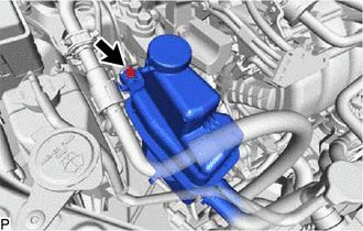
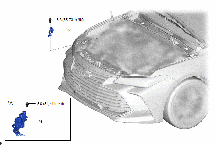
*1 | INVERTER RESERVE TANK SUB-ASSEMBLY |
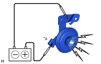
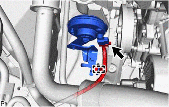
*2 | SECURITY HORN ASSEMBLY |
 |
N*m (kgf*cm, ft.*lbf): Specified torque |
- | - |
Inspection
INSPECTION
PROCEDURE
1. INSPECT SECURITY HORN ASSEMBLY
| (a) Check the operation of the security horn assembly. OK:
If the result is not as specified, replace the security horn assembly. |
|
Installation
INSTALLATION
PROCEDURE
1. INSTALL SECURITY HORN ASSEMBLY
(a) Engage the 2 guides and install the security horn assembly with the bolt.
Torque:
8.3 N·m {85 kgf·cm, 73 in·lbf}
(b) Connect the connector.
(c) Engage the clamp.
2. INSTALL INVERTER RESERVE TANK SUB-ASSEMBLY (for HV Model)
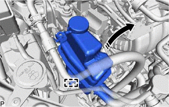
(a) Engage the pin as shown in the illustration.
 |
Install in this Direction |
(b) Install the inverter reserve tank assembly with the bolt.
Torque:
5.0 N·m {51 kgf·cm, 44 in·lbf}
Removal
REMOVAL
PROCEDURE
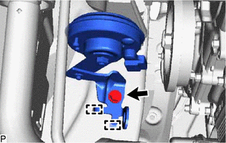
1. SEPARATE INVERTER RESERVE TANK SUB-ASSEMBLY (for HV Model)
| (a) Remove the bolt. |
|
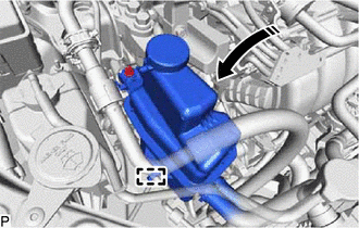
(b) Disengage the pin to separate the inverter reserve tank assembly from the engine mounting insulator sub-assembly RH as shown in the illustration.
 |
Disconnect in this Direction |
NOTICE:
2. REMOVE SECURITY HORN ASSEMBLY
| (a) Disengage the clamp. |
|
(b) Disconnect the connector.
| (c) Remove the bolt. |
|
(d) Disengage the 2 guides to remove the security horn assembly.
Toyota Avalon (XX50) 2019-2022 Service & Repair Manual > Heating / Air Conditioning: Solar Sensor
Components COMPONENTS ILLUSTRATION *A w/o Front No. 3 Speaker *B w/ Front No. 3 Speaker *1 AUTOMATIC LIGHT CONTROL SENSOR *2 FRONT DOOR OPENING TRIM WEATHERSTRIP LH *3 FRONT DOOR OPENING TRIM WEATHERSTRIP RH *4 FRONT PILLAR GARNISH LH *5 FRONT PILLAR GARNISH RH *6 NO. 1 DEFROSTER NOZZLE GARNISH *7 C ...