Toyota Avalon (XX50): Engine Immobiliser System Signal (Some Circuit Quantity, Reported via Serial Data) Invalid (B279986). Check For Intermittent Problems. Customer Problem Analysis Check
Engine Immobiliser System Signal (Some Circuit Quantity, Reported via Serial Data) Invalid (B279986)
DESCRIPTION
If there is a
communication malfunction between the ECM and certification ECU (smart
key ECU assembly), or when the communication ID codes do not match, the
ECM stores this DTC.
|
DTC No. | Detection Item |
DTC Detection Condition | Trouble Area |
Note |
| B279986 |
Engine Immobiliser System Signal (Some Circuit Quantity, Reported via Serial Data) Invalid |
Either of the following conditions is met (1 trip detection logic*):
- A malfunction is detected in the communication or communication lines
between the ECM and certification ECU (smart key ECU assembly).
- The communication ID codes of the ECM and certification ECU (smart key ECU assembly) do not match.
|
- Certification ECU (smart key ECU assembly)
- ECM
- Wire harness or connector
| DTC output confirmation operation (Perform either of the following):
- Start the engine and wait for 10 seconds. If there is a malfunction, the
engine will stop (communication begins within 3 seconds of the engine
start operation being performed, and DTCs are stored after 6 seconds).
- Connect the cable to the negative (-) battery terminal, start the engine
and wait for 10 seconds (communication begins within 3 seconds of the
engine switch being turned on (IG), and DTCs are stored after 6
seconds).
|
- *: Only output while a malfunction is present.
Vehicle Condition and Fail-safe Operation when Malfunction Detected |
Vehicle Condition when Malfunction Detected |
Fail-safe Operation when Malfunction Detected |
|
Engine cannot be started |
- |
Related Data List and Active Test |
DTC No. | Data List and Active Test |
|
B279986 | - |
WIRING DIAGRAM

CAUTION / NOTICE / HINT
NOTICE:
- When using the Techstream with the engine switch off, connect the
Techstream to the DLC3 and turn a courtesy light switch on and off at
intervals of 1.5 seconds or less until communication between the
Techstream and the vehicle begins. Then select the vehicle type under
manual mode and enter the following menus: Body Electrical / Smart Key.
While using the Techstream, periodically turn a courtesy light switch on
and off at intervals of 1.5 seconds or less to maintain communication
between the Techstream and the vehicle.
- The smart key system (for Start Function, Gasoline Model) uses the LIN
communication system and CAN communication system. Inspect the
communication function by following How to Proceed with Troubleshooting.
Troubleshoot the smart key system (for Start Function, Gasoline Model)
after confirming that the communication systems are functioning
properly.
Click here 
- Before replacing the ECM or certification ECU (smart key ECU assembly), refer to Registration.
Click here 
- After performing repairs, confirm that no DTCs are output by performing "DTC Output Confirmation Operation".
HINT:
When DTC
B279986 and the certification ECU (smart key ECU assembly) DTC are
output simultaneously, first perform troubleshooting for the
certification ECU (smart key ECU assembly) DTC.
PROCEDURE
| 1. |
REGISTER ECU COMMUNICATION ID |
(a) Register the ECU communication ID code.
Click here 
|
NEXT |
 | |
| 2. |
CHECK CERTIFICATION ECU (SMART KEY ECU ASSEMBLY) (TERMINAL EFII) |
(a) Using an oscilloscope, check the waveform.

|
*a | Component with harness connected
(Certification ECU (Smart Key ECU Assembly)) |
*b | Waveform |
|
*c | Approximately 160 ms. |
*d | Approximately 270 ms. |
OK:
|
Tester Connection | Condition |
Tool Setting | Specified Condition |
|
A10-3 (EFII) - Body ground |
Engine switch on (IG) |
2 V/DIV., 500 ms./DIV. |
Pulse generation (See waveform) |
|
Result | Proceed to |
|
Normal waveform | A |
|
Terminal EFII stuck low (2.4 V or less) |
B |
| Waveform not output, or has abnormal wavelength or shape |
C |
| B |
 | GO TO STEP 6 |
| C |
 | REPLACE ECM |
|
A |
 | |
| 3. |
CHECK CERTIFICATION ECU (SMART KEY ECU ASSEMBLY) (TERMINAL EFIO) |
(a) Using an oscilloscope, check the waveform.

|
*a | Component with harness connected
(Certification ECU (Smart Key ECU Assembly)) |
*b | Waveform |
|
*c | Approximately 160 ms. |
*d | Approximately 270 ms. |
OK:
|
Tester Connection | Condition |
Tool Setting | Specified Condition |
|
A10-4 (EFIO) - Body ground |
Engine switch turned on (IG) using registered electrical key transmitter sub-assembly |
2 V/DIV., 500 ms./DIV. |
Pulse generation (See waveform) |
| NG |
 | REPLACE CERTIFICATION ECU (SMART KEY ECU ASSEMBLY) |
|
OK |
 | |
| 4. |
REGISTER ECU COMMUNICATION ID |
(a) Register the ECU communication ID code.
Click here 
|
NEXT |
 | |
| 5. |
CHECK WHETHER ENGINE STARTS |
(a) Using an electrical key transmitter sub-assembly which is registered to the vehicle, turn the engine switch on (IG).
(b) Check that the engine starts 5 seconds after the engine switch turned on (IG).
OK:
Engine starts normally.
| OK |
 | END (ECU COMMUNICATION ID HAS NOT BEEN REGISTERED) |
| NG |
 | REPLACE ECM |
(a) Disconnect the A18 ECM connector.
(b) Measure the voltage according to the value(s) in the table below.
Standard Voltage:
|
Tester Connection | Condition |
Specified Condition |
|
A18-45 (IMO) - Body ground |
Engine switch turned on (IG) using registered electrical key transmitter sub-assembly |
Terminal IMO stuck low (2.4 V or less) |
|
Terminal IMO stuck high (12 V) or abnormal waveform |
|
Result | Proceed to |
|
Terminal IMO stuck low (2.4 V or less) |
A |
| Terminal IMO stuck high (12 V) or abnormal waveform |
B |
| B |
 | REPLACE ECM |
|
A |
 | |
| 7. |
CHECK HARNESS AND CONNECTOR (CERTIFICATION ECU (SMART KEY ECU ASSEMBLY) - ECM) |
(a) Disconnect the A10 certification ECU (smart key ECU assembly) connector.
(b) Measure the resistance according to the value(s) in the table below.
Standard Resistance:
|
Tester Connection | Condition |
Specified Condition |
|
A10-3 (EFII) - A18-45 (IMO) |
Always | Below 1 Ω |
|
A10-3 (EFII) or A18-45 (IMO) - Other terminals and body ground |
Always | 10 kΩ or higher |
| OK |
 | REPLACE CERTIFICATION ECU (SMART KEY ECU ASSEMBLY) |
| NG |
 | REPAIR OR REPLACE HARNESS OR CONNECTOR |
Check For Intermittent Problems
CHECK FOR INTERMITTENT PROBLEMS
NOTICE:
- Operation history is stored in the RAM or EEPROM of the certification
ECU (smart key ECU assembly). As the cause of a malfunction stored in
the RAM will be cleared when the cable is disconnected from the negative
(-) battery terminal, do not disconnect the cable from the negative (-)
battery terminal before checking and recording are complete.
- If the vehicle or vehicle controls are operated (for example, during
initial inspection when the vehicle is brought in for repair) before
operation history has been read and saved, the operation history
information could be lost.
- The operation history function uses the current system time of the
Techstream and the time counter inside the controlling ECU to calculate
the time shown in the operation history. For this reason, before reading
the operation history, first make sure that the Techstream system clock
is accurately set to the current time.
OPERATION HISTORY
HINT:
The
certification ECU (smart key ECU assembly) stores the operation history
of the smart key system and it can be read using the Techstream.
(a) Connect the Techstream to the DLC3.
(b) Turn the engine switch on (IG).
(c) Turn the Techstream on.
(d) Enter the following menus: Body Electrical / Smart Key / Utility / Operation History / (desired item).
Body Electrical > Smart Key > Utility
|
Tester Display |
| Operation History |
(e) According to the display on the Techstream, read and save the operation history.
|
Operation History List |
|
Auto Entry Mode Switch History |
|
Auto Entry Wireless Operation History |
|
Warning Operation History |
|
Engine Start |
|
Customize(Auto Entry Cancel) |
|
Customize(Door Unlock Mode Switch) |
|
Radio Wave Interference (RF Signal Received) |
|
Engine Start (inactive) |
|
Remote Engine Starter (inactive) |
|
Auto Entry Unlock (inactive) |
|
Registration Function (Reason for Non-operation) |
|
Auto Entry Lock (inactive) |
|
Engine Start Inactive (Brake/Clutch System) |
|
Radio Wave Interference (RF Reception Not Available) |
|
Engine Start Inactive (Steering Lock System) |
HINT:
Some items may not be displayed depending on the specifications of the vehicle.
SYMPTOM SIMULATION
Click here 
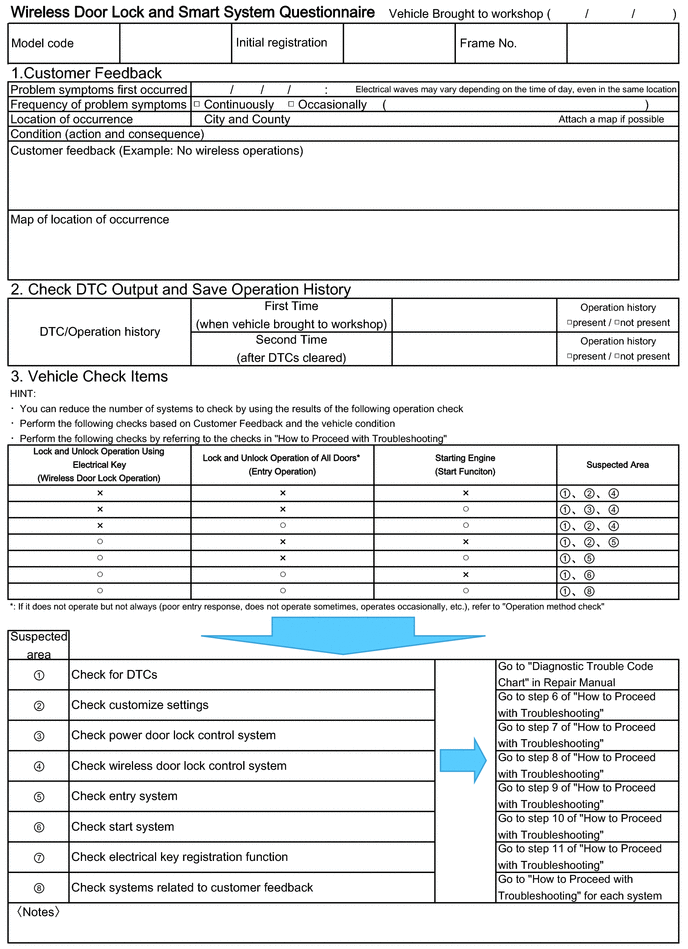
Customer Problem Analysis Check
CUSTOMER PROBLEM ANALYSIS CHECK


HINT:
Be
sure to ask the customer in detail about the following points
concerning the vehicle operating conditions, environment and problem,
and then check for DTCs.
- If the entry unlock function does not operate.
- If the power source mode does not change even though the engine switch was pressed (does not change to on (ACC)).
- If the entry lock function does not operate.
- If the entry lock/unlock function does not operate for all doors.
- If both the entry lock and unlock functions do not operate.
- If the wireless lock and unlock functions do not operate.
- If the engine cannot be started the push-button start function.
- If an engine start was attempted by holding the electrical key
transmitter sub-assembly near the engine switch and then pressing the
engine switch.
- If the warning buzzers inside the vehicle do not sound.
- If the warning buzzers outside the vehicle do not sound.
- If the steering wheel does not unlock.
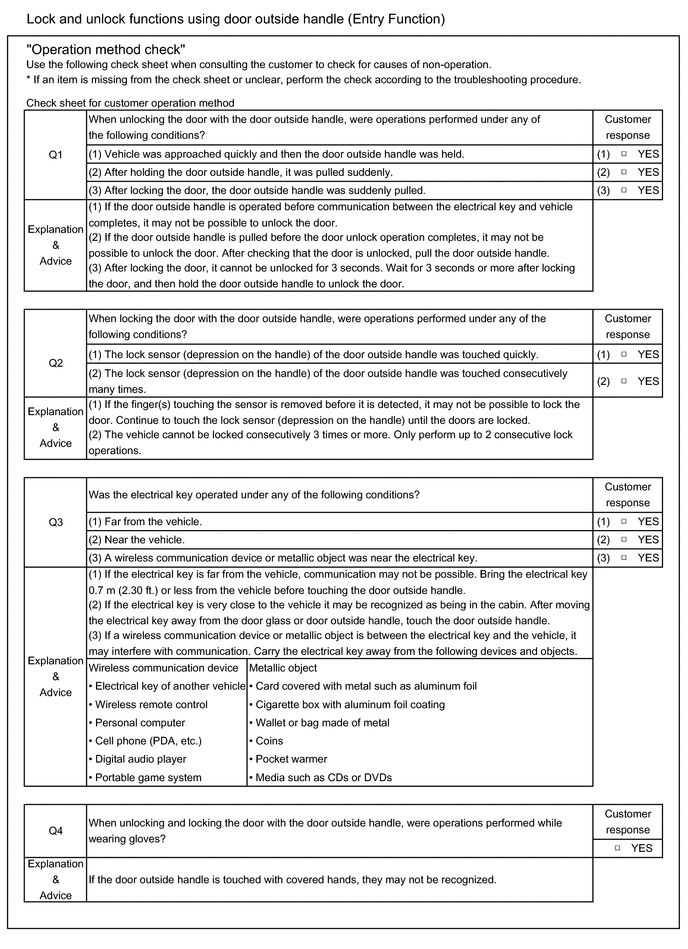
If it is suspected that wave
interference is likely, be sure to ask the customer in detail about the
following points concerning the vehicle operating conditions,
environment and problem.
- Specific locations where the system does not operate (such as near TV
towers, large video displays, wireless garage door opener systems,
wireless security cameras, home security systems, etc.).
- Specific times when the system does not operate.
- If the symptoms occurred immediately after purchase or only recently.
- If the system does not operate only when near specific vehicles (there
may be wave interference from the wireless systems of other vehicles).
- If the system operates intermittently.
- If the electrical key transmitter sub-assembly is bundled together with other items.
- If the electrical key transmitter sub-assembly is carried together with
other electronic devices, such as cell phones, personal computers,
portable music players, other electrical key transmitter sub-assemblies,
etc. (make sure to keep the electrical key transmitter sub-assembly at
least 0.1 m (0.328 ft.) away from such items).
- Where the electrical key transmitter sub-assembly is being kept when not
in use: If the electrical key transmitter sub-assembly is being placed
within 1 m (3.28 ft.) of items such as TVs, DVD recorders, induction
cookers, rice cookers, dishwashers, modems, cell phones, personal
computers, microwave ovens, desk or floor lamps, cordless telephones,
etc.
- If there are electronic devices that transmit radio waves placed in the vehicle.
- When the transmitter battery was last replaced. The transmitter battery
capacity can be approximated using the Key Low Battery Data List item.
Click here 
- If the customer installed any optional components (theft deterrent devices, wireless fog lights, etc.) to the vehicle.


