Operation Check
OPERATION CHECK
CHECK CUSTOMIZE PARAMETERS
(a) The operation check below is based on the non-customized initial condition of the vehicle.
Click here 
CHECK PUSH-BUTTON START FUNCTION
(a) Check the push-button start function:
(1)
Get into the vehicle while carrying the electrical key transmitter
sub-assembly with the engine switch off. With the shift lever in P,
check that the key indicator display is displayed when the brake pedal
is depressed. Check that the engine starts when the engine switch is
pressed after the key indicator display is displayed on the
multi-information display.
(2) While carrying the
electrical key transmitter sub-assembly, check that the power source
mode changes in the following order when the engine switch is pressed
with the brake pedal released: off → on (ACC) → on (IG) → off.
HINT:
If
the engine switch is pressed with the engine switch on (IG) and the
shift lever not in P, the power source mode will not change to off, but
to on (ACC).
(3) With the shift lever in P, check that the steering lock operates when a door is opened.
HINT:
When
the engine switch is pressed after the vehicle is stopped, the engine
will stop and all power will turn off. However, if the shift lever is
not in P when the engine switch is pressed with the vehicle stopped, the
power source mode will not change to off, but to on (ACC).
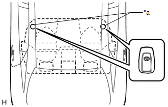
(4)
Check the push-button start function operation range for the front
side. Place the electrical key transmitter sub-assembly at either
inspection point so that it is facing the direction shown in the
illustration, and then check that the engine can be started.
NOTICE:
Even
if the electrical key transmitter sub-assembly is in a vehicle interior
detection area, it may not be properly detected if it is on the
instrument panel, in the glove box or on the floor.
HINT:
- Communication may not be possible if the electrical key transmitter
sub-assembly is within 0.2 m (0.656 ft.) of the No. 1 indoor electrical
key antenna assembly (front floor).
Click here 
- Perform this inspection for both inspection points.
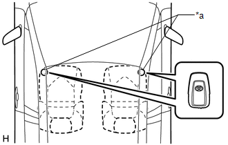
(5)
Check the push-button start function operation range for the rear side.
Place the electrical key transmitter sub-assembly at either inspection
point so that it is facing the direction shown in the illustration, and
then check that the engine can be started.
NOTICE:
Even
if the electrical key transmitter sub-assembly is in a vehicle interior
detection area, it may not be properly detected if it is on the
instrument panel, in the glove box or on the floor.
HINT:
- Communication may not be possible if the electrical key transmitter
sub-assembly is within 0.2 m (0.656 ft.) of the center of the No. 1
indoor electrical key antenna assembly (rear floor).
Click here 
- Perform this inspection for both inspection points.
CHECK POWER SOURCE MODE CHANGING FUNCTION
(a) Check the engine switch.
(1) Check that the power source mode changes according to the chart below.
|
Shift Position | Brake Pedal |
Power Source Mode when Engine Switch Pressed |
|
P | Released |
Off → on (ACC) → on (IG) → off |
|
P | Released |
Engine running → off |
|
P | Released |
On (ACC)* → off |
|
P | Depressed |
Off → engine starts |
|
P | Depressed |
On (ACC) → engine starts |
|
P | Depressed |
On (IG) → engine starts |
|
P | Depressed |
Engine running → off |
|
P | Depressed |
On (ACC)* → off |
|
N | Released |
Off
→ on (ACC) → on (IG) (after power source mode changes to on (IG), power
source mode changes between on (IG) and on (ACC) every time engine
switch is pressed) |
| N |
Released | Engine running → on (ACC) |
|
N | Depressed |
Off → engine starts |
|
N | Depressed |
On (ACC) → engine starts |
|
N | Depressed |
On (IG) → engine starts |
|
N | Depressed |
Engine running → on (ACC) |
|
Not P or N | Released |
Off
→ on (ACC) → on (IG) (after power source mode changes to on (IG), power
source mode changes between on (IG) and on (ACC) every time engine
switch is pressed) |
| Not P or N |
Released | Engine running → on (ACC) |
|
Not P or N | Depressed |
Off → on (IG) |
|
Not P or N | Depressed |
On (ACC) → on (IG) |
|
Not P or N | Depressed |
Engine running → on (ACC) |
HINT:
*: This situation is only applicable when the power source mode has changed from on (IG) to on (ACC).
CHECK TRANSMITTER BATTERY SAVING MODE FUNCTION
(a) Check the transmitter battery saving mode function:
(1)
Press the unlock switch of the electrical key transmitter sub-assembly
twice while pressing the lock switch and check that the electrical key
transmitter sub-assembly LED blinks 4 times and enters transmitter
battery saving mode.
(2) Check that the smart key system does not operate while in transmitter battery saving mode.
HINT:
To cancel transmitter battery saving mode, press a switch of the electrical key transmitter sub-assembly.
CHECK ENTRY CANCEL FUNCTION
(a) Disable the smart key system and check that all functions of the smart key system no longer operate.
Click here 
HINT:
When
the smart key system is disabled, it is possible to lock and unlock the
doors with the wireless function, and the engine can be started by
holding the electrical key transmitter sub-assembly near the engine
switch.
CHECK KEY DIAGNOSTIC MODE
Click here

Power Source Mode does not Change to ON (ACC)
DESCRIPTION
If the engine
switch is pressed with the electrical key transmitter sub-assembly in
the cabin, the certification ECU (smart key ECU assembly) receives a
signal and changes the power source mode.
Related Data List and Active Test Items |
Problem Symptom | Data List and Active Test |
|
Power source mode does not change to on (ACC) but does change to on (IG) | Power Source Control
- Power Supply Condition
- ACC Relay Monitor
Starting Control
|
WIRING DIAGRAM
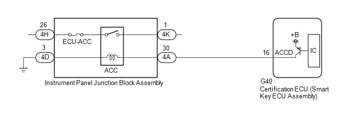
CAUTION / NOTICE / HINT
NOTICE:
- When using the Techstream with the engine switch off, connect the
Techstream to the DLC3 and turn a courtesy light switch on and off at
intervals of 1.5 seconds or less until communication between the
Techstream and the vehicle begins. Then select the vehicle type under
manual mode and enter the following menus: Body Electrical / Smart Key.
While using the Techstream, periodically turn a courtesy light switch on
and off at intervals of 1.5 seconds or less to maintain communication
between the Techstream and the vehicle.
- The smart key system (for Start Function, Gasoline Model) uses the LIN
communication system and CAN communication system. Inspect the
communication function by following How to Proceed with Troubleshooting.
Troubleshoot the smart key system (for Start Function, Gasoline Model)
after confirming that the communication systems are functioning
properly.
Click here 
- Make sure that no DTCs are output. If any DTCs are output, proceed to Diagnostic Trouble Code Chart.
- If the smart key system (for Start Function, Gasoline Model) has been
disabled, enable the system before performing troubleshooting.
Click here 
- Inspect the fuses for circuits related to this system before performing the following procedure.
- Before replacing the certification ECU (smart key ECU assembly), refer to Registration.
Click here 
- After completing repairs, confirm that the problem does not recur.
- After performing repairs, confirm that no DTCs are output by performing "DTC Output Confirmation Operation."
PROCEDURE
(a) Using the Techstream, check for certification ECU (smart key ECU assembly) DTCs.
Body Electrical > Power Source Control > Trouble Codes Body
Electrical > Smart Key > Trouble Codes Body Electrical >
Starting Control > Trouble Codes |
Result | Proceed to |
|
DTCs are not output | A |
|
Smart key system (for Start Function, Gasoline Model) DTCs are output |
B |
| B |
 | GO TO DIAGNOSTIC TROUBLE CODE CHART |
|
A |
 | |
| 2. |
CHECK CERTIFICATION ECU (SMART KEY ECU ASSEMBLY) |
| (a) Connect the G40 certification ECU (smart key ECU assembly) connector. |
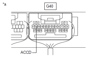 |
|
*a | Component with harness connected (Certification ECU (Smart Key ECU Assembly)) | | |
(b) Measure the voltage according to the value(s) in the table below.
Standard Voltage:
|
Tester Connection | Condition |
Specified Condition |
|
G40-16 (ACCD) - Body ground |
Engine switch on (ACC) → Engine switch on (IG) |
1 V or less → 9 V or higher |
| NG |
 | REPLACE CERTIFICATION ECU (SMART KEY ECU ASSEMBLY) |
|
OK |
 | |
| 3. |
CHECK
HARNESS AND CONNECTOR (CERTIFICATION ECU (SMART KEY ECU ASSEMBLY) -
INSTRUMENT PANEL JUNCTION BLOCK ASSEMBLY, BATTERY AND BODY GROUND) |
(a) Disconnect the G40 certification ECU (smart key ECU assembly) connector.
(b) Disconnect the 4A, 4D and 4K instrument panel junction block assembly connectors.
(c) Measure the resistance according to the value(s) in the table below.
Standard Resistance:
|
Tester Connection | Condition |
Specified Condition |
|
G40-16 (ACCD) - 4A-30 |
Always | Below 1 Ω |
|
4D-3 - Body ground | Always |
Below 1 Ω |
|
G40-16 (ACCD) or 4A-30 - Other terminals and body ground |
Always | 10 kΩ or higher |
(d) Measure the voltage according to the value(s) in the table below.
Standard Voltage:
|
Tester Connection | Condition |
Specified Condition |
|
4K-1 - Body ground | Always |
11 to 14 V |
| NG |
 | REPAIR OR REPLACE HARNESS OR CONNECTOR |
|
OK |
 | |
| 4. |
CHECK INSTRUMENT PANEL JUNCTION BLOCK ASSEMBLY (ACC RELAY) |
(a) Remove the instrument panel junction block assembly.
Click here

(b) Connect all of the instrument panel junction block assembly connectors.
(c) Measure the voltage according to the value(s) in the table below.
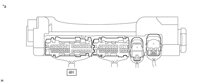
|
*a | Component without harness connected
(Instrument Panel Junction Block Assembly) |
- | - |
Standard Voltage:
|
Tester Connection | Condition |
Specified Condition |
|
4H-26 - Body ground | Engine switch on (IG) |
11 to 14 V |
| OK |
 | USE SIMULATION METHOD TO CHECK |
| NG |
 | REPLACE INSTRUMENT PANEL JUNCTION BLOCK ASSEMBLY |


