Check For Intermittent Problems
CHECK FOR INTERMITTENT PROBLEMS
NOTICE:
- If the vehicle or vehicle controls are operated (for example, during
initial inspection when the vehicle is brought in for repair) before
operation history has been read and saved, the operation history
information could be lost.
- The operation history function uses the current system time of the
Techstream and the time counter inside the controlling ECU to calculate
the times shown in the operation history. For this reason, before
reading the operation history, first make sure that the Techstream
system clock is accurately set to the current time.
- Before replacing the main body ECU (multiplex network body ECU), refer to Registration.
Click here 
- Make sure the engine switch is off, all the doors and the hood are
closed and all the doors have been locked by wireless operation or entry
operation.
Operation History
HINT:
The
main body ECU (multiplex network body ECU) stores Operation History,
which can be read using the Techstream, when a malfunction of the theft
deterrent system occurs.
(a) Connect the Techstream to the DLC3.
(b) Turn the engine switch on (IG).
(c) Turn the Techstream on.
(d) Enter the following menus: Body Electrical / Main Body / Utility / Operation History.
Body Electrical > Main Body > Utility
|
Tester Display |
| Operation History |
(e) According to the display on the Techstream, read and save the operation history.
|
Operation History List |
|
Battery Desorption |
|
Hood Open |
| Luggage Open |
|
Door Open |
| Door Unlock |
|
IG |
| Intrusion Sensor Detect |
|
Glass Sensor |
| Tilt Sensor |
|
Intrusion Sensor Sound Detect |
|
Intrusion Sensor Detect at Window Open |
|
Panic Alarm |
HINT:
Depending on the specifications of the vehicle some items may not be displayed.
Symptom Simulation
Click here
Customize Parameters
CUSTOMIZE PARAMETERS
CUSTOMIZE THEFT DETERRENT SYSTEM
NOTICE:
- When the customer requests a change in a function, first make sure that the function can be customized.
- Be sure to make a note of the current settings before customizing.
- When troubleshooting a function, first make sure that the function is set to the default setting.
HINT:
The following items can be customized.
(a) Customizing with the Techstream
(1) Connect the Techstream to the DLC3.
(2) Turn the engine switch on (IG).
(3) Turn the Techstream on.
(4) Enter the following menus: Customize Setting / Wireless Door Lock.
(5) Select the setting by referring to the table below.
Wireless Door Lock
|
Tester Display | Description |
Default | Setting |
ECU |
| Panic Function |
This
function makes it possible to operate the theft deterrent system by
continuously pressing the panic switch on the key for 0.8 seconds |
ON | 0:OFF,1:ON |
Main body ECU (Multiplex network body ECU) |
Data List / Active Test
DATA LIST / ACTIVE TEST
DATA LIST
HINT:
Using
the Techstream to read the Data List allows the values or states of
switches, sensors, actuators and other items to be read without removing
any parts. This non-intrusive inspection can be very useful because
intermittent conditions or signals may be discovered before parts or
wiring is disturbed. Reading the Data List information early in
troubleshooting is one way to save diagnostic time.
NOTICE:
In
the table below, the values listed under "Normal Condition" are
reference values. Do not depend solely on these reference values when
deciding whether a part is faulty or not.
(a) Connect the Techstream to the DLC3.
(b) Turn the engine switch on (IG).
(c) Turn the Techstream on.
(d) Enter the following menus: Body Electrical / Main Body / Data List.
(e) Read the Data List according to the display on the Techstream.
Body Electrical > Main Body > Data List
|
Tester Display | Measurement Item |
Range | Normal Condition |
Diagnostic Note |
|
ACC SW | Engine switch |
OFF or ON | OFF: Engine switch off
ON: Engine switch on (ACC) |
- |
| IG SW |
Engine switch | OFF or ON |
OFF: Engine switch off or ACC ON: Engine switch on (IG) |
- |
| RR Door Courtesy SW |
Rear door courtesy light switch assembly (for RH) |
OFF or ON | OFF: Rear door RH closed
ON: Rear door RH open |
- |
| RL Door Courtesy SW |
Rear door courtesy light switch assembly (for LH) |
OFF or ON | OFF: Rear door LH closed
ON: Rear door LH open |
- |
| FR Door Lock Pos |
Front door RH unlock detection switch |
LOCK or UNLOCK | LOCK: Front door RH locked
UNLOCK: Front door RH unlocked |
- |
| FR Door Courtesy SW |
Front door courtesy light switch assembly (for RH) |
OFF or ON | OFF: Front door RH closed
ON: Front door RH open |
- |
| FL Door Lock Pos |
Front door LH unlock detection switch |
LOCK or UNLOCK | LOCK: Front door LH locked
UNLOCK: Front door LH unlocked |
- |
| FL Door Courtesy SW |
Front door courtesy light switch assembly (for LH) |
OFF or ON | OFF: Front door LH closed
ON: Front door LH open |
- |
| Hood Courtesy SW |
Engine hood courtesy switch |
OFF or ON | OFF: Engine hood closed
ON: Engine hood open |
- |
| RR-Door Lock Pos SW |
Rear door RH unlock detection switch |
OFF or ON | OFF: Rear door RH locked
ON: Rear door RH unlocked |
- |
| RL-Door Lock Pos SW |
Rear door LH unlock detection switch |
OFF or ON | OFF: Rear door LH locked
ON: Rear door LH unlocked |
- |
| Luggage Courtesy SW |
Luggage compartment door courtesy light switch signal |
OFF or ON | OFF: Luggage compartment door closed
ON: Luggage compartment door open |
- |
| Intrusion Sens OFF SW |
Intrusion sensor cancel switch* |
OFF or ON | OFF: Intrusion sensor cancel switch off
ON: Intrusion sensor cancel switch on |
Not applicable |
|
Glass Break Sensor Detection |
Glass breakage sensor breakage detection* |
OFF or ON | OFF: Glass breakage sensor breakage not detected
ON: Glass breakage sensor breakage detected |
Not applicable |
|
Intrusion Sensor | Detection status of the intrusion sensor (theft warning ultrasonic sensor)* |
OFF or ON | OFF: Intrusion not detected
ON: Intrusion detected |
Not applicable |
|
Intrusion Sen Conn | Intrusion sensor (theft warning ultrasonic sensor) connection* |
OFF or ON | OFF: Intrusion sensor not connected
ON: Intrusion sensor connected |
Not applicable |
|
Intrusion Sensor Sound Detect |
Sound detection status of the intrusion sensor (theft warning ultrasonic sensor)* |
OFF or ON | OFF: Sound not detected
ON: Sound detected | Not applicable |
|
Panic Function | Setting of customize setting "Panic Function" |
OFF or ON | Customize setting displayed |
- |
| Intrusion Win Opened |
Setting of customize setting "Intrusion Win Opened"* |
OFF or ON | Customize setting displayed |
Not applicable |
|
Communication Theft Deterrent |
Connection status between theft deterrent ECU and main body ECU (multiplex network body ECU)* |
STOP or OK | STOP: Communication stopped
OK: Normal communication |
Not applicable |
- *: Although the item is displayed on the Techstream, it is not applicable to this vehicle.
ACTIVE TEST
HINT:
Using
the Techstream to perform Active Tests allows relays, VSVs, actuators
and other items to be operated without removing any parts. This
non-intrusive functional inspection can be very useful because
intermittent operation may be discovered before parts or wiring is
disturbed. Performing Active Tests early in troubleshooting is one way
to save diagnostic time. Data List information can be displayed while
performing Active Tests.
(a) Connect the Techstream to the DLC3.
(b) Turn the engine switch on (IG).
(c) Turn the Techstream on.
(d) Enter the following menus: Body Electrical / Main Body or Smart Key / Active Test.
(e) Perform the Active Test according to the display on the Techstream.
Body Electrical > Main Body > Active Test
|
Tester Display | Measurement Item |
Control Range | Diagnostic Note |
|
Security Indicator | Security indicator* |
OFF/ON | Not applicable |
|
Security Horn2 | Theft warning siren assembly* |
OFF/ON | Not applicable |
|
Vehicle Horn | Vehicle horns |
OFF/ON | - |
|
Security Horn | Security horn assembly |
OFF/ON | - |
|
Power For Intrusion Sensor |
Intrusion sensor (theft warning ultrasonic sensor) power supply* |
OFF/ON | Not applicable |
- *: Although the item is displayed on the Techstream, it is not applicable to this vehicle.
Body Electrical > Smart Key > Active Test
|
Tester Display | Measurement Item |
Control Range | Diagnostic Note |
|
Immobiliser Indicator | Security indicator |
OFF/ON | - |
Diagnosis System
DIAGNOSIS SYSTEM
CHECK DLC3
(a) Check the DLC3.
Click here 
INSPECT BATTERY VOLTAGE
(a) Measure the battery voltage.
Standard Voltage:
11 to 14 V
If the voltage is below 11 V, replace the battery.
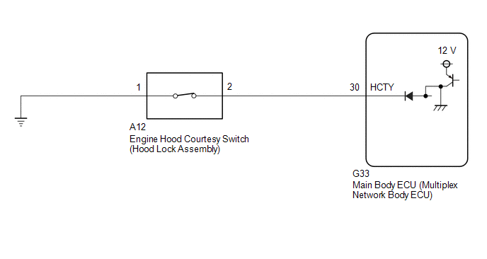
Engine Hood Courtesy Switch Circuit
DESCRIPTION
The engine hood
courtesy switch is built into the hood lock assembly. This switch turns
on when the engine hood is closed and turns off when the engine hood is
opened.
WIRING DIAGRAM
CAUTION / NOTICE / HINT
NOTICE:
Before replacing the main body ECU (multiplex network body ECU), refer to Registration.
Click here 
PROCEDURE
| 1. |
READ VALUE USING TECHSTREAM (HOOD COURTESY SW) |
(a) Connect the Techstream to the DLC3.
(b) Turn the engine switch on (IG).
(c) Turn the Techstream on.
(d) Enter the following menus: Body Electrical / Main Body / Data List.
(e) Read the Data List according to the display on the Techstream.
Body Electrical > Main Body > Data List
|
Tester Display | Measurement Item |
Range | Normal Condition |
Diagnostic Note |
|
Hood Courtesy SW | Engine hood courtesy switch |
OFF or ON | OFF: Engine hood closed
ON: Engine hood open |
- |
Body Electrical > Main Body > Data List
|
Tester Display |
| Hood Courtesy SW |
OK:
The Techstream display changes correctly in response to the engine hood courtesy switch (hood lock assembly) status.
| OK |
 | REPLACE MAIN BODY ECU (MULTIPLEX NETWORK BODY ECU) |
|
NG |
 | |
| 2. |
INSPECT ENGINE HOOD COURTESY SWITCH (HOOD LOCK ASSEMBLY) |
(a) Remove the hood lock assembly.
Click here
(b) Inspect the engine hood courtesy switch (hood lock assembly).
Click here
| NG |
| REPLACE ENGINE HOOD COURTESY SWITCH (HOOD LOCK ASSEMBLY) |
|
OK | |
| |
| 3. |
CHECK
HARNESS AND CONNECTOR (MAIN BODY ECU (MULTIPLEX NETWORK BODY ECU) -
ENGINE HOOD COURTESY SWITCH (HOOD LOCK ASSEMBLY) AND BODY GROUND) |
(a) Disconnect the G33 main body ECU (multiplex network body ECU) connector.
(b) Measure the resistance according to the value(s) in the table below.
Standard Resistance:
|
Tester Connection | Condition |
Specified Condition |
|
G33-30 (HCTY) - A12-2 |
Always | Below 1 ╬® |
|
G33-30 (HCTY) or A12-2 - Body ground |
Always | 10 k╬® or higher |
|
A12-1 - Other terminals and body ground |
Always | Below 1 ╬® |
| OK |
| REPLACE MAIN BODY ECU (MULTIPLEX NETWORK BODY ECU) |
| NG |
| REPAIR OR REPLACE HARNESS OR CONNECTOR |
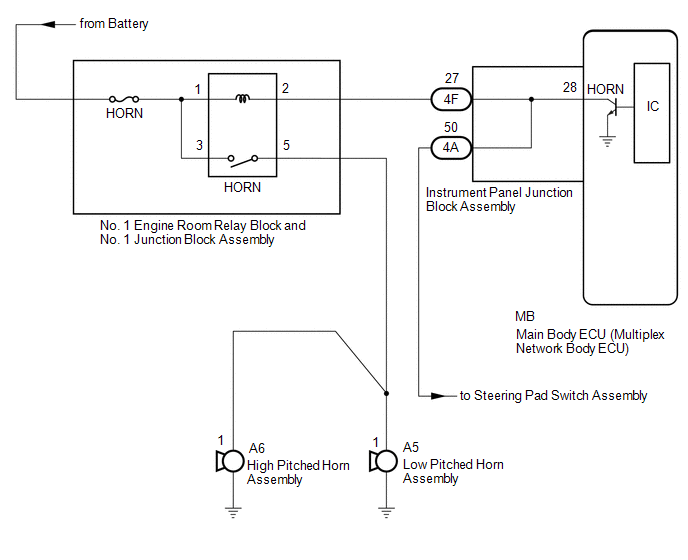
Horn Circuit
DESCRIPTION
When the theft
deterrent system is switched from the armed state to the alarm sounding
state, the main body ECU (multiplex network body ECU) transmits a signal
to cause the horns to sound at intervals of 0.4 seconds.
WIRING DIAGRAM
CAUTION / NOTICE / HINT
NOTICE:
- Before replacing the main body ECU (multiplex network body ECU), refer to Registration.
Click here 
- Inspect the fuses for circuits related to this system before performing the following procedure.
PROCEDURE
(a) Press the horn switch and check if the horns sound.
|
Result | Proceed to |
|
Horns sound | A |
|
Horns do not sound | B |
| B |
 | GO TO HORN SYSTEM |
|
A |
 | |
| 2. |
INSPECT INSTRUMENT PANEL JUNCTION BLOCK ASSEMBLY |
(a) Remove the main body ECU (multiplex network body ECU).
Click here
|
*a | Component without harness connected
(Instrument Panel Junction Block Assembly) |
- | - |
(b) Disconnect the 4F instrument panel junction block assembly connector.
(c) Measure the resistance according to the value(s) in the table below.
Standard Resistance:
|
Tester Connection | Condition |
Specified Condition |
|
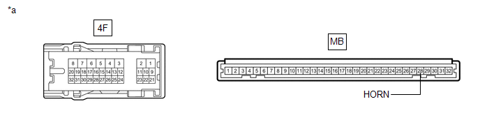
4F-27 - MB-28 (HORN) |
Always | Below 1 ╬® |
| OK |
| REPLACE MAIN BODY ECU (MULTIPLEX NETWORK BODY ECU) |
| NG |
| REPLACE INSTRUMENT PANEL JUNCTION BLOCK ASSEMBLY |
How To Proceed With Troubleshooting
CAUTION / NOTICE / HINT
HINT:
- Use this procedure to troubleshoot the theft deterrent system.
- *: Use the Techstream.
PROCEDURE
|
1. | VEHICLE BROUGHT TO WORKSHOP |
|
NEXT |
 | |
| 2. |
CUSTOMER PROBLEM ANALYSIS CHECK |
HINT:
- In troubleshooting, confirm that the problem symptoms have been
accurately identified. Preconceptions should be discarded in order to
make an accurate judgment. To clearly understand what the problem
symptoms are, it is extremely important to ask the customer about the
problem and the conditions at the time the malfunction occurred.
- Gather as much information as possible for reference. Past problems that seem unrelated may also help in some cases.
- The following 5 items are important points for problem analysis:
| What |
Vehicle model, system name |
| When |
Date, time, occurrence frequency, whether the problem occurred recently or has been occurring for a long time |
|
Where | Whether the problem occurs at a specific location |
|
Under what conditions? | Whether the doors were locked or unlocked, whether the engine switch was on (IG), whether the engine has started. |
|
How did it happen? | Problem symptoms |
|
NEXT | |
| |
| 3. |
READ AND SAVE OPERATION HISTORY |
NOTICE:
- If the vehicle or vehicle controls are operated (for example, during
initial inspection when the vehicle is brought in for repair) before
operation history has been read and saved, the operation history
information could be lost.
- The operation history function uses the current system time of the
Techstream and the time counter inside the controlling ECU to calculate
the times shown in the operation history. For this reason, before
reading the operation history, first make sure that the Techstream
system clock is accurately set to the current time.
(a) Read and save operation history using the Techstream.
Click here

Body Electrical > Main Body > Utility
|
Tester Display |
| Operation History |
|
NEXT | |
| |
(a) Measure the battery voltage.
Standard Voltage:
11 to 14 V
If the voltage is below 11 V, recharge or replace the battery before proceeding to the next step.
(b) Check the fuses and relays.
(c)
Check the connector connections and terminals to make sure that there
are no abnormalities such as loose connections, deformation, etc.
|
NEXT | |
| |
|
NEXT | |
| |
| 6. |
INSPECT COMMUNICATION FUNCTION OF CAN COMMUNICATION SYSTEM* |
(a) Using the Techstream, check for CAN communication system DTCs.
Click here
|
Result | Proceed to |
|
CAN DTCs are not output |
A |
| CAN DTCs are output |
B |
| B |
 | GO TO CAN COMMUNICATION SYSTEM |
|
A | |
| |
| 7. |
CHECK POWER DOOR LOCK CONTROL SYSTEM |
(a) Check the power door lock control system.
Click here
OK:
Power door lock control system is normal
| NG |
| GO TO POWER DOOR LOCK CONTROL SYSTEM |
|
OK | |
| |
| 8. |
CHECK WIRELESS DOOR LOCK CONTROL SYSTEM |
(a) Check the wireless door lock control system.
Click here
OK:
Wireless door lock control system is normal
| NG |
| GO TO WIRELESS DOOR LOCK CONTROL SYSTEM |
|
OK | |
| |
| 9. |
CHECK SMART KEY SYSTEM (for Entry Function) |
(a) Check the smart key system (for Entry Function).
Click here
OK:
Smart key system (for Entry Function) is normal
| NG |
| GO TO SMART KEY SYSTEM (for Entry Function) |
|
OK | |
| |
| 10. |
CHECK SMART KEY SYSTEM (for Start Function) |
(a) Check the smart key system (for Start Function).
Click here
OK:
Smart key system (for Start Function) is normal
| NG |
| GO TO SMART KEY SYSTEM (for Start Function) |
|
OK | |
| |
| 11. |
CHECK LIGHTING SYSTEM (EXT) |
(a) Check the lighting system (EXT).
w/ Cornering Light: Click here
w/o Cornering Light: Click here
OK:
Lighting system (EXT) is normal
|
Result | Proceed to |
|
OK | A |
|
NG (w/ Cornering Light) |
B |
| NG (w/o Cornering Light) |
C |
| B |
| GO TO LIGHTING SYSTEM (EXT) |
| C |
| GO TO LIGHTING SYSTEM (EXT) |
|
A | |
| |
| 12. |
CHECK LIGHTING SYSTEM (INT) |
(a) Check the lighting system (INT).
Click here
OK:
Lighting system (INT) is normal
| NG |
| GO TO LIGHTING SYSTEM (INT) |
|
OK | |
| |
| 13. |
CHECK LUGGAGE COMPARTMENT DOOR OPENER SYSTEM |
(a) Check the luggage compartment door opener system.
Click here
OK:
Luggage compartment door opener system is normal
| NG |
| GO TO LUGGAGE COMPARTMENT DOOR OPENER SYSTEM |
|
OK | |
| |
(a) Check the horn system.
OK:
Horn system is normal
| NG | | GO TO HORN SYSTEM |
|
OK | |
| |
| 15. |
PROBLEM SYMPTOMS TABLE |
(a) Refer to Problem Symptoms Table.
Click here
|
Result | Proceed to |
|
Fault is not listed in Problem Symptoms Table (Fault can be simulated) |
A |
| Fault is not listed in Problem Symptoms Table (Fault cannot be simulated) |
B |
| Fault is listed in Problem Symptoms Table |
C |
| B |
| CHECK FOR INTERMITTENT PROBLEMS |
| C |
| GO TO STEP 17 |
|
A | |
| |
| 16. |
PERFORM OVERALL ANALYSIS AND TROUBLESHOOTING* |
(a) System Description
Click here
(b) Terminals of ECU
Click here
(c) Data List / Active Test
Click here
(d) Inspection
|
NEXT | |
| |
|
NEXT | |
| |
| NEXT |
| END |
Improper Operation
DESCRIPTION
If the alarm function of the theft deterrent system operates unintentionally, one of the following may be the cause.
- Short to ground in any door courtesy light switch circuit or the engine hood courtesy switch (hood lock assembly) circuit.
- Unstable main body ECU (multiplex network body ECU) power source voltage.
HINT:
Preconditions for arming preparation:
- Make sure the engine switch is off, all the doors and the hood are
closed and all the doors have been locked by wireless operation or entry
operation.
WIRING DIAGRAM

CAUTION / NOTICE / HINT
NOTICE:
- Before replacing the main body ECU (multiplex network body ECU), refer to Registration.
Click here 
- The theft deterrent system uses the CAN communication system. Inspect
the communication function by following How to Proceed with
Troubleshooting. Troubleshoot the theft deterrent system after
confirming that the communication system is functioning properly.
Click here
- The following troubleshooting procedure is based on the assumption that
systems related to the theft deterrent system are normal. Confirm that
the systems related to the theft deterrent system are not malfunctioning
before performing the following procedure.
Click here
- If the vehicle or vehicle controls are operated (for example, during
initial inspection when the vehicle is brought in for repair) before
operation history has been read and saved, the operation history
information could be lost.
- The operation history function uses the current system time of the
Techstream and the time counter inside the controlling ECU to calculate
the times shown in the operation history. For this reason, before
reading the operation history, first make sure that the Techstream
system clock is accurately set to the current time.
PROCEDURE
|
1. | CHECK THEFT DETERRENT SYSTEM OPERATION HISTORY |
(a)
Use the Techstream to check the theft deterrent system operation
history around the time the customer reported the malfunction to have
occurred.
Click here
(1)
Check if there is operation history around the time that the customer
reported the malfunction to have occurred, and perform an operation
check.
|
Result | Proceed to |
|
There
is operation history around the time that the customer reported the
malfunction to have occurred, but a malfunction could not be identified
during the operation check. | A |
|
There
is operation history around the time that the customer reported the
malfunction to have occurred, and the malfunction was identified during
the operation check. | B |
|
There is no operation history around the time that the customer reported the malfunction to have occurred. |
C |
| B |
 | GO TO STEP 7 |
| C |
| END |
|
A |
 | |
| 2. |
CHECK SECURITY INDICATOR LIGHT OPERATION |
(a) Check that the security indicator light is illuminated when the theft deterrent system is in the arming preparation state.
Click here
(b) Check that the security indicator light blinks when the theft deterrent system is in the arming state.
Click here
|
State of Theft Deterrent System |
Contents | Security Indicator Light Condition |
|
Disarmed state (1), (2) |
Theft deterrent system is unset. |
- Off (Immobiliser system unset)
- Blinking (Immobiliser system set)
|
| Arming preparation state |
Standby
period after theft deterrent system set conditions are met but before
theft deterrent system is actually set (approximately 30 seconds). (Theft detection not possible) |
On |
| Armed state |
Theft deterrent system is set. (Theft detection is possible) |
Blinking (Immobiliser system set) |
|
Alarm sounding state | Theft attempt is detected, and alarm operates using turn signal lights, security horn assembly and vehicle horns.
(Alarm sounds for 57 seconds) |
On |
| NG |
| GO TO OTHER PROBLEM |
|
OK | |
| |
| 3. |
READ VALUE USING TECHSTREAM (Hood Courtesy SW) |
(a) Connect the Techstream to the DLC3.
(b) Turn the engine switch on (IG).
(c) Turn the Techstream on.
(d) Enter the following menus: Body Electrical / Main Body / Data List.
(e) Read the Data List according to the display on the Techstream.
Body Electrical > Main Body > Data List
|
Tester Display | Measurement Item |
Range | Normal Condition |
Diagnostic Note |
|
Hood Courtesy SW | Engine hood courtesy switch |
OFF or ON | OFF: Engine hood closed
ON: Engine hood open |
- |
Body Electrical > Main Body > Data List
|
Tester Display |
| Hood Courtesy SW |
OK:
The Techstream display changes correctly in response to the engine hood courtesy switch (hood lock assembly) status.
| NG |
| GO TO STEP 5 |
|
OK | |
| |
| 4. |
INTERVIEW THE CUSTOMER |
(a)
If the problem symptoms could not be reproduced, explain to the
customer the details of the operation history, such as the input signal
timings of the key, etc.
Click here
OK:
Cause was identified
| OK | |
END |
| NG |
| CHECK FOR INTERMITTENT PROBLEMS |
| 5. |
INSPECT ENGINE HOOD COURTESY SWITCH (HOOD LOCK ASSEMBLY) |
(a) Remove the hood lock assembly.
Click here
(b) Inspect the engine hood courtesy switch (hood lock assembly).
Click here
| NG |
| REPLACE HOOD LOCK ASSEMBLY |
|
OK | |
| |
| 6. |
CHECK
HARNESS AND CONNECTOR (ENGINE HOOD COURTESY SWITCH (HOOD LOCK ASSEMBLY)
- MAIN BODY ECU (MULTIPLEX NETWORK BODY ECU) AND BODY GROUND) |
(a) Disconnect the A12 engine hood courtesy switch (hood lock assembly) connector.
(b) Disconnect the G33 main body ECU (multiplex network body ECU) connector.
(c) Measure the resistance according to the value(s) in the table below.
Standard Resistance:
|
Tester Connection | Condition |
Specified Condition |
|
G33-30 (HCTY) - A12-2 (+) |
Always | Below 1 ╬® |
|
G33-30 (HCTY) or A12-2 (+) - Other terminals and body ground |
Always | 10 k╬® or higher |
|
A12-1 (E) - Body ground |
Always | Below 1 ╬® |
| OK |
| REPLACE MAIN BODY ECU (MULTIPLEX NETWORK BODY ECU) |
| NG |
| REPAIR OR REPLACE HARNESS OR CONNECTOR |
| 7. |
INTERVIEW THE CUSTOMER |
(a)
If the problem symptoms could not be reproduced, explain to the
customer the details of the operation history, such as the input signal
timings of the key, etc.
Click here
OK:
Cause was identified
| OK | |
END |
| NG |
| CHECK FOR INTERMITTENT PROBLEMS |
Parts Location
PARTS LOCATION
ILLUSTRATION
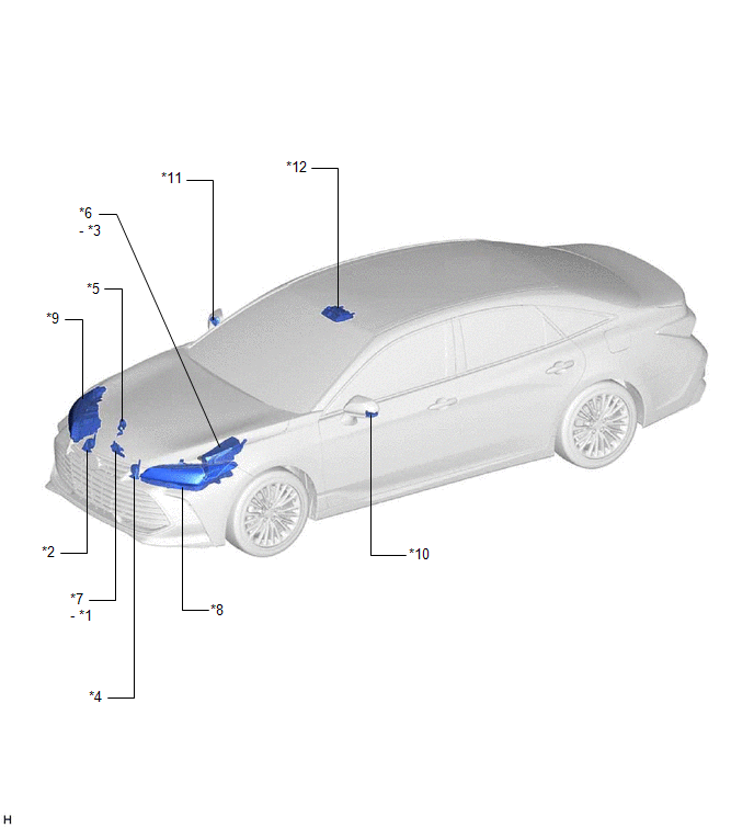
|
*1 | ENGINE HOOD COURTESY SWITCH |
*2 | HIGH PITCHED HORN ASSEMBLY |
|
*3 | HORN RELAY |
*4 | LOW PITCHED HORN ASSEMBLY |
|
*5 | SECURITY HORN ASSEMBLY |
*6 | NO. 1 ENGINE ROOM RELAY BLOCK AND NO. 1 JUNCTION BLOCK ASSEMBLY
- HORN FUSE |
|
*7 | HOOD LOCK ASSEMBLY |
*8 | HEADLIGHT ASSEMBLY LH
- LOW BEAM - TURN SIGNAL LIGHT |
|
*9 | HEADLIGHT ASSEMBLY RH
- LOW BEAM - TURN SIGNAL LIGHT |
*10 | SIDE TURN SIGNAL LIGHT ASSEMBLY LH |
|
*11 | SIDE TURN SIGNAL LIGHT ASSEMBLY RH |
*12 | ROOF CONSOLE BOX SUB-ASSEMBLY
- INTERIOR LIGHT |
ILLUSTRATION
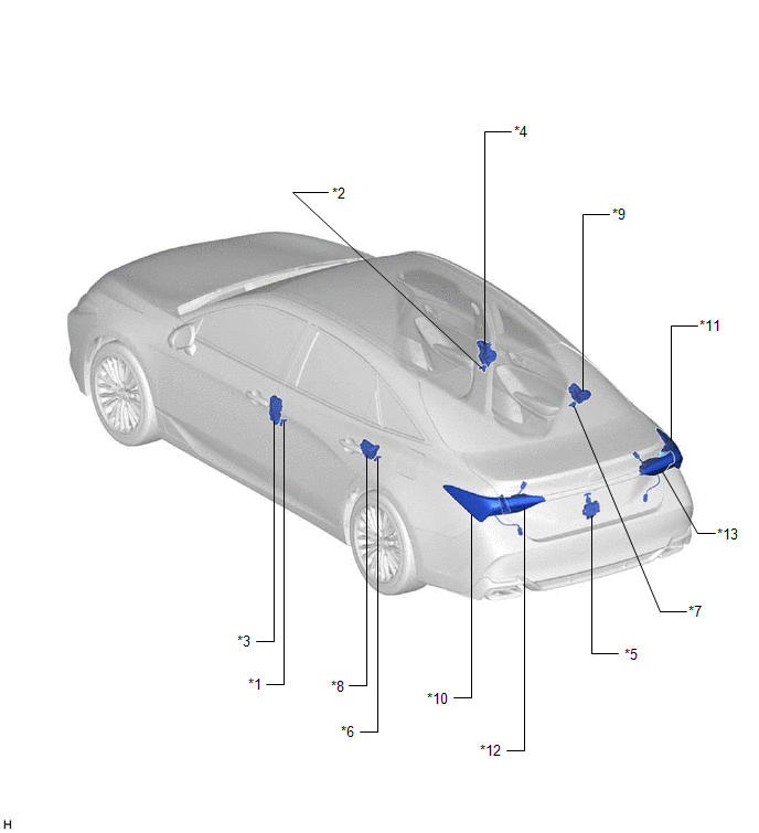
|
*1 | FRONT DOOR COURTESY LIGHT SWITCH ASSEMBLY (for LH) |
*2 | FRONT DOOR COURTESY LIGHT SWITCH ASSEMBLY (for RH) |
|
*3 | FRONT DOOR LOCK WITH MOTOR ASSEMBLY LH |
*4 | FRONT DOOR LOCK WITH MOTOR ASSEMBLY RH |
|
*5 | LUGGAGE COMPARTMENT DOOR LOCK ASSEMBLY |
*6 | REAR DOOR COURTESY LIGHT SWITCH ASSEMBLY (for LH) |
|
*7 | REAR DOOR COURTESY LIGHT SWITCH ASSEMBLY (for RH) |
*8 | REAR DOOR LOCK WITH MOTOR ASSEMBLY LH |
|
*9 | REAR DOOR LOCK WITH MOTOR ASSEMBLY RH |
*10 | REAR COMBINATION LIGHT ASSEMBLY LH
- TAILLIGHT - TURN SIGNAL LIGHT |
|
*11 | REAR COMBINATION LIGHT ASSEMBLY RH
- TAILLIGHT - TURN SIGNAL LIGHT |
*12 | REAR LIGHT ASSEMBLY LH |
|
*13 | REAR LIGHT ASSEMBLY RH |
- | - |
ILLUSTRATION
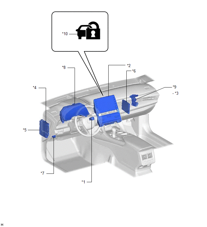
|
*1 | ENGINE SWITCH |
*2 | RADIO AND DISPLAY RECEIVER ASSEMBLY |
|
*3 | S-HORN RELAY |
*4 | MAIN BODY ECU (MULTIPLEX NETWORK BODY ECU) |
|
*5 | INSTRUMENT PANEL JUNCTION BLOCK ASSEMBLY
- ECU-DCC NO. 2 FUSE - ECU-ACC FUSE - ECU-IG1 NO. 4 FUSE
- S-HORN FUSE | *6 |
CERTIFICATION ECU (SMART KEY ECU ASSEMBLY) |
|
*7 | DLC3 |
*8 | COMBINATION METER ASSEMBLY |
|
*9 | NO. 5 RELAY BLOCK |
*10 | SECURITY INDICATOR LIGHT |
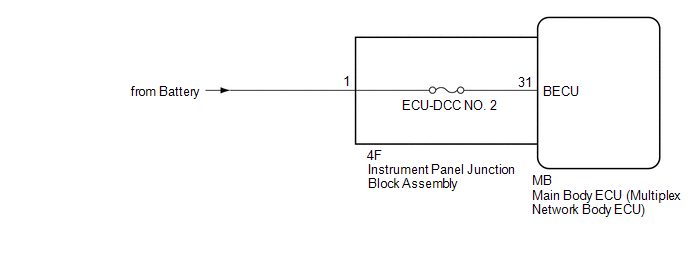
Power Source Circuit
DESCRIPTION
Based on
changes in the power source voltage, the main body ECU (multiplex
network body ECU) can detect if the battery has been disconnected and
reconnected.
WIRING DIAGRAM
CAUTION / NOTICE / HINT
NOTICE:
- Before replacing the main body ECU (multiplex network body ECU), refer to Registration.
Click here 
- Inspect the fuses for circuits related to this system before performing the following procedure.
PROCEDURE
|
1. | CHECK HARNESS AND CONNECTOR (POWER SUPPLY) |
(a) Disconnect the 4F instrument panel junction block assembly connector.
(b) Measure the voltage according to the value(s) in the table below.
Standard Voltage:
|
Tester Connection | Condition |
Specified Condition |
|
4F-1 - Body ground | Always |
8.5 V or higher |
| NG |
 | REPAIR OR REPLACE HARNESS OR CONNECTOR |
|
OK |
 | |
| 2. |
INSPECT INSTRUMENT PANEL JUNCTION BLOCK ASSEMBLY |
(a) Remove the main body ECU (multiplex network body ECU).
Click here
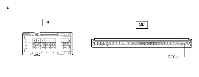
|
*a | Component without harness connected
(Instrument Panel Junction Block Assembly) |
- | - |
(b) Measure the resistance according to the value(s) in the table below.
Standard Resistance:
|
Tester Connection | Condition |
Specified Condition |
|
4F-1 - MB-31 (BECU) | Always |
Below 1 ╬® |
| OK |
| REPLACE MAIN BODY ECU (MULTIPLEX NETWORK BODY ECU) |
| NG |
| REPLACE INSTRUMENT PANEL JUNCTION BLOCK ASSEMBLY |
Precaution
PRECAUTION
PRECAUTION FOR DISCONNECTING CABLE FROM NEGATIVE BATTERY TERMINAL
NOTICE:
When
disconnecting the cable from the negative (-) battery terminal,
initialize the following systems after the cable is reconnected.
|
System Name | See Procedure |
|
Lane Departure Alert System (w/ Steering Control) |
 |
|
Intelligent Clearance Sonar System |
|
Parking Assist Monitor System |
|
Panoramic View Monitor System |
|
Pre-collision System |
|
Lighting System (for Gasoline Model with Cornering Light) |
Problem Symptoms Table
PROBLEM SYMPTOMS TABLE
NOTICE:
Before replacing the main body ECU (multiplex network body ECU), refer to Registration.
Click here 
HINT:
- Troubleshooting of the theft deterrent system is based on the premise
that the power door lock control system and the wireless door lock
control system are operating normally. Accordingly, before
troubleshooting the theft deterrent system, first make certain that the
power door lock control system and the wireless door lock control system
are operating normally.
- Use the table below to help determine the cause of problem symptoms. If
multiple suspected areas are listed, the potential causes of the
symptoms are listed in order of probability in the "Suspected Area"
column of the table. Check each symptom by checking the suspected areas
in the order they are listed. Replace parts as necessary.
- Inspect the fuses and relays related to this system before inspecting the suspected areas below.
Theft Deterrent System |
Symptom | Suspected Area |
Link |
|
Theft deterrent system cannot be set |
Refer to "Security Indicator Light Does not Blink" |
|
|
Refer to "Front Door Courtesy Switch Circuit" |
|
|
Refer to "Rear Door Courtesy Switch Circuit" |
|
|
Refer to "Luggage Compartment Door Courtesy Switch Circuit" |
|
|
Front door lock with motor assembly |
|
|
Rear door lock with motor assembly |
|
|
Luggage compartment door lock assembly |
|
|
Refer to "Engine Hood Courtesy Switch Circuit" |
|
|
Security indicator light does not blink when theft deterrent system is set |
Refer to "Security Indicator Light Does not Blink" |
|
|
Alarm sounding state cannot be canceled when engine switch is turned on (IG) |
Refer to "Smart Key System (for Start Function)" |
|
|
Certification ECU (Smart key ECU assembly) |
- |
| If
the symptom(s) still occur after the above areas are inspected and
proved to be normal, replace the main body ECU (multiplex network body
ECU) |
|
|
Theft deterrent system can be set even when door is open |
Refer to "Front Door Courtesy Switch Circuit" |
|
|
Refer to "Rear Door Courtesy Switch Circuit" |
|
|
Refer to "Luggage Compartment Door Courtesy Switch Circuit" |
|
|
If
the symptom(s) still occur after the above areas are inspected and
proved to be normal, replace the main body ECU (multiplex network body
ECU) |
|
|
Theft deterrent system can be set even when engine hood is open |
Refer to "Engine Hood Courtesy Switch Circuit" |
|
|
Vehicle horns do not sound while theft deterrent system is in alarm sounding state |
Refer to "Horn Circuit" |
|
|
Low beams do not blink while theft deterrent system is in alarm sounding state |
Refer to "LIGHTING SYSTEM"*1 |
|
|
Refer to "LO-beam Headlight does not Illuminate"*2 |
|
|
If
the symptom(s) still occur after the above area is inspected and proved
to be normal, replace the main body ECU (multiplex network body ECU) |
|
|
Taillights do not blink while theft deterrent system is in alarm sounding state |
Refer to "Taillight Relay Circuit"*1 |
|
|
Refer to "Taillight Relay Circuit"*2 |
|
|
If
the symptom(s) still occur after the above area is inspected and proved
to be normal, replace the main body ECU (multiplex network body ECU) |
|
|
Hazard warning lights do not flash while theft deterrent system is in alarm sounding state |
Combination meter assembly |
- |
| If
the symptom(s) still occur after the above area is inspected and proved
to be normal, replace the main body ECU (multiplex network body ECU) |
|
|
Interior lights does not light up while theft deterrent system is in alarm sounding state |
Refer to "Interior Light Circuit" |
|
|
If
the symptom(s) still occur after the above area is inspected and proved
to be normal, replace the main body ECU (multiplex network body ECU) |
|
|
Security horn does not sound while theft deterrent system is in alarm sounding state |
Refer to "Security Horn Circuit" |
|
|
Low beams blink even when theft deterrent system is not set |
Refer to "LIGHTING SYSTEM"*1 |
|
|
Refer to "LO-beam Headlight does not Illuminate"*2 |
|
|
If
the symptom(s) still occur after the above area is inspected and proved
to be normal, replace the main body ECU (multiplex network body ECU) |
|
|
Taillights blink even when theft deterrent system is not set |
Refer to "Taillight Relay Circuit"*1 |
|
|
Refer to "Taillight Relay Circuit"*2 |
|
|
If
the symptom(s) still occur after the above area is inspected and proved
to be normal, replace the main body ECU (multiplex network body ECU) |
|
|
Hazard warning lights flash even when theft deterrent system is not set |
Combination meter assembly |
- |
| If
the symptom(s) still occur after the above area is inspected and proved
to be normal, replace the main body ECU (multiplex network body ECU) |
|
|
Interiors light comes on even when theft deterrent system is not set |
Refer to "Interior Light Circuit" |
|
|
If
the symptom(s) still occur after the above area is inspected and proved
to be normal, replace the main body ECU (multiplex network body ECU) |
|
|
The vehicle does not enter the alarm sounding state as the battery is reconnected |
Check the battery |
|
|
Refer to "Power Source Circuit" |
|
- *1: w/ Cornering Light
- *2: w/o Cornering Light
Security Horn Circuit
DESCRIPTION
When the theft
deterrent system is switched from the armed state to the alarm sounding
state, the main body ECU (multiplex network body ECU) transmits a signal
to cause the security horn assembly to sound at intervals of 0.4
seconds.
WIRING DIAGRAM
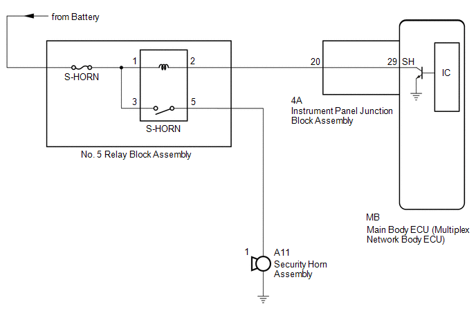
CAUTION / NOTICE / HINT
NOTICE:
- Before replacing the main body ECU (multiplex network body ECU), refer to Registration.
Click here 
- Inspect the fuses for circuits related to this system before performing the following procedure.
PROCEDURE
|
1. | PERFORM ACTIVE TEST USING TECHSTREAM (SECURITY HORN) |
(a) Connect the Techstream to the DLC3.
(b) Turn the engine switch on (IG).
(c) Turn the Techstream on.
(d) Enter the following menus: Body Electrical / Main Body / Active Test.
(e) Perform the Active Test according to the display on the Techstream.
Body Electrical > Main Body > Active Test
|
Tester Display | Measurement Item |
Control Range | Diagnostic Note |
|
Security Horn | Security horn Assembly |
OFF/ON | - |
Body Electrical > Main Body > Active Test
|
Tester Display |
| Security Horn |
OK:
The security horn assembly sounds and stops correctly when operated through the Techstream.
| OK |
 | REPLACE MAIN BODY ECU (MULTIPLEX NETWORK BODY ECU) |
|
NG |
 | |
| 2. |
INSPECT SECURITY HORN ASSEMBLY |
(a) Remove the security horn assembly.
Click here
(b) Inspect the security horn assembly.
Click here
| NG |
| REPLACE SECURITY HORN ASSEMBLY |
|
OK | |
| |
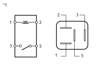
| (a) Remove the S-HORN relay from the No. 5 relay block. |
|
(b) Measure the resistance according to the value(s) in the table below.
Standard Resistance:
|
Tester Connection | Condition |
Specified Condition |
|
3 - 5 | Battery voltage not applied between terminals 1 and 2 |
10 k╬® or higher |
|
3 - 5 | Battery voltage applied between terminals 1 and 2 |
Below 1 ╬® |
| NG |
| REPLACE S-HORN RELAY |
|
OK | |
| |
| 4. |
INSPECT INSTRUMENT PANEL JUNCTION BLOCK ASSEMBLY |
(a) Remove the main body ECU (multiplex network body ECU).
Click here
|
*a | Component without harness connected (Instrument Panel Junction Block Assembly) |
- | - |
(b) Disconnect the 4A instrument panel junction block assembly connector.
(c) Measure the resistance according to the value(s) in the table below.
Standard Resistance:
|
Tester Connection | Condition |
Specified Condition |
|
4A-20 - MB-29 (SH) | Always |
Below 1 ╬® |
| NG |
| REPLACE INSTRUMENT PANEL JUNCTION BLOCK ASSEMBLY |
|
OK | |
| |
| 5. |
CHECK HARNESS AND CONNECTOR (BATTERY - S-HORN RELAY) |
| (a) Measure the voltage according to the value(s) in the table below.
Standard Voltage: |
Tester Connection | Condition |
Specified Condition | |
No. 5 relay block S-HORN relay terminal 1 - Body ground |
Always | 11 to 14 V | |
No. 5 relay block S-HORN relay terminal 3 - Body ground |
Always | 11 to 14 V | |
|
| NG |
| REPAIR OR REPLACE HARNESS OR CONNECTOR |
|
OK | |
| |
| 6. |
CHECK HARNESS AND CONNECTOR (S-HORN RELAY - SECURITY HORN ASSEMBLY) |
| (a) Measure the resistance according to the value(s) in the table below.
Standard Resistance: |
Tester Connection | Condition |
Specified Condition | |
No. 5 relay block S-HORN relay terminal 5 - A11-1 |
Always | Below 1 ╬® | |
No. 5 relay block S-HORN relay terminal 5 or A11-1 - Other terminals and body ground |
Always | 10 k╬® or higher | |
|
| NG |
| REPAIR OR REPLACE HARNESS OR CONNECTOR |
|
OK | |
| |
| 7. |
CHECK HARNESS AND CONNECTOR (S-HORN RELAY - INSTRUMENT PANEL JUNCTION BLOCK ASSEMBLY) |
| (a) Measure the resistance according to the value(s) in the table below.
Standard Resistance: |
Tester Connection | Condition |
Specified Condition | |
No. 5 relay block S-HORN relay terminal 2 - 4A-20 |
Always | Below 1 ╬® | |
No. 5 relay block S-HORN relay terminal 2 or 4A-20 - Other terminals and body ground |
Always | 10 k╬® or higher | |
|
| OK |
| REPLACE MAIN BODY ECU (MULTIPLEX NETWORK BODY ECU) |
| NG |
| REPAIR OR REPLACE HARNESS OR CONNECTOR |
System Description
SYSTEM DESCRIPTION
OUTLINE OF THEFT DETERRENT SYSTEM
(a) Disarmed state:
- The alarm function is not operating.
- The theft deterrent system is not operating.
(b) Arming preparation state:
- The time until the system goes into the armed state.
- The theft deterrent system is not operating.
(c) Armed state:
- The theft deterrent system is operating.
(d) Alarm sounding state:
- The alarm function is operating.
Alarm time:
Approximately 57 seconds
Alarm Methods |
Alarm Method |
| Blinking |
|
Turn Signal Lights | Blinking |
|
Interior Lights | Illuminating |
|
Vehicle Horns | Sounding (Approximately 0.4-second cycles) |
|
Security Horn Assembly | Sounding
(Approximately 0.4-second cycles) |
FUNCTION OF MAIN COMPONENTS
|
Component | Function |
|
Security indicator light | Informs driver of theft deterrent system status. |
|
Security horn assembly | Sounds when attempted break-in or theft is detected. |
|
Low beams | Blink when attempted break-in or theft is detected. |
|
Taillights |
- Blink when attempted break-in or theft is detected.
- Come on when theft deterrent system has entered alarm sounding state.
|
| Turn signal lights |
Blink when attempted break-in or theft is detected. |
|
Interior lights | Comes on when attempted break-in or theft is detected. |
|
Vehicle horns | Sound when attempted break-in or theft is detected. |
- Front door courtesy light switch assembly (for LH/RH)
- Rear door courtesy light switch assembly (for LH/RH)
| Detects door status (open or closed). |
|
Door unlock detection switch | Detects door status (locked or unlocked). |
|
Engine hood courtesy switch (Hood lock assembly) |
Detects engine hood status (open or closed). |
|
Certification ECU (Smart key ECU assembly) |
- Receives wireless door lock/unlock signal.
- Receives entry door lock/unlock signal.
|
| Luggage compartment door lock assembly |
Detects luggage compartment door status (open or closed). |
ACTIVE ARMING MODE
(a) Active arming mode:
This system operates as described in the diagram below when one of the items for each condition is met.
HINT:
- The term "all doors" used in this section refers to the driver door, front passenger door, rear door LH and rear door RH.
- Using the remote door lock and unlock is also considered to be a wireless lock/unlock operation.*
- *: for Toyota Entune Remote Connect Compatible Type
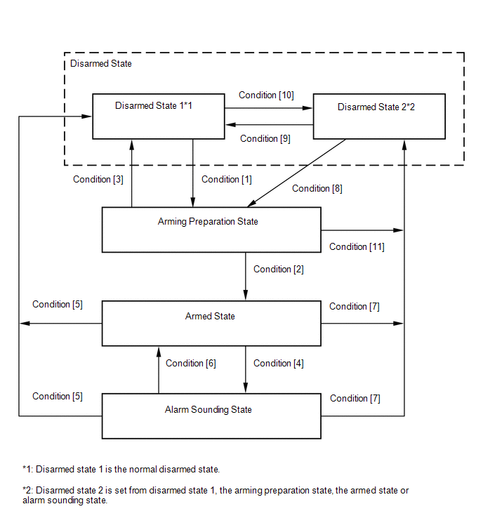
|
Condition | Item |
|
Condition [1] | In disarmed state 1, when the engine switch is turned off, the system state is changed if the following condition is met:
- With all doors, the luggage compartment door and the engine hood closed,
all doors are locked by wireless operation, the smart key system or key
linked power door lock operation.
In disarmed state 1, when the engine
switch is off, the engine hood and the luggage compartment door are
closed and all doors are locked, the system state is changed if the
following condition is met:
- All doors are closed when any door is open.
|
| Condition [2] |
- Approximately 30 seconds elapse.
|
| Condition [3] |
- All doors are unlocked by wireless operation, the smart key system or key linked power door lock operation.
- Any door is unlocked.
- Any door is opened.
- The engine switch is pushed.
- The engine switch is turned on (ACC) or on (IG). (Not using the remote start.*)
- The battery is reconnected.
|
| Condition [4] |
- The engine hood is opened when it was closed.
- The luggage compartment door is opened when it was closed.
- The battery is reconnected while the engine hood or the luggage compartment door is open or any door is unlocked.
- Any door is opened when all doors are closed.
- Any door is unlocked when all doors are locked.
- When 5 seconds or more have elapsed since the engine switch is pressed,
the power source mode is changed from off to on (IG) without pressing
the engine switch. (Not using the remote start.*)
|
| Condition [5] |
- The engine switch is turned on (IG) and the engine is running at 550 rpm for 2 seconds or more.
- All doors are unlocked by wireless operation, the smart key system or key linked power door lock operation.
- The engine switch is turned on (ACC) or on (IG) within 5 seconds after
the engine switch is pushed. (Not using the remote start.*)
|
| Condition [6] |
- After approximately 57 seconds, the alarm stops and the system returns to the armed state.
|
| Condition [7] |
The luggage compartment door is opened by wireless operation or the smart key system. |
|
Condition [8] |
- The luggage compartment door is closed when the engine hood is closed.
- The engine hood is closed when the luggage compartment door is closed.
|
| Condition [9] |
- Any door is unlocked when all doors are locked.
- Any door is opened.
- The engine switch is pushed.
- The engine switch is turned on (ACC) or on (IG). (Not using the remote start.*)
- The battery is reconnected.
- All doors are unlocked by wireless operation, the smart key system or key linked power door lock operation.
|
| Condition [10] |
In disarmed state 1, when the engine switch is turned off, the system state is changed if the following condition is met:
- With all doors closed and the engine hood and the luggage compartment
door open, all doors are locked by wireless operation, the smart key
system or key linked power door lock operation.
In disarmed state 1, when the engine
switch is off, the engine hood and the luggage compartment door are open
and all doors are locked, the system state is changed if the following
condition is met:
- All doors are closed when any door is open.
|
| Condition [11] |
- The engine hood is opened.
- The luggage compartment door is opened.
- The luggage compartment door is opened by wireless operation or the smart key system.
|
- *: for Toyota Entune Remote Connect Compatible Type
FORCED DOOR LOCK CONTROL
(a)
The forced door lock control prevents the vehicle from being tampered
with. Immediately after a door is unlocked (armed state), all doors are
forced to lock by a forced door lock signal.
(1) If the following conditions are met, the forced door lock control is operated.
- The theft deterrent system is in the armed state.
- Any door is unlocked.
ALARM MEMORY FUNCTION
(a)
If the alarm is set off (tampering is detected) while the theft
deterrent system is in the armed state, it will be stored by the alarm
memory function. Whenever the theft deterrent system is canceled, the
alarm memory function causes the taillights to light up for 2 seconds in
order to inform the user that the alarm has been set off.
(1) Condition that cause the taillights to light up for 2 seconds:
The theft deterrent system has entered the alarm sounding state (tampering has been detected) at least once.
HINT:
Active arming mode: See Active Arming Mode.
PANIC ALARM CONTROL
(a) Panic alarm control makes it possible to voluntarily set off the panic alarm by pressing the panic switch on the key.
(1) Conditions that cause panic alarm control to set off the panic alarm:
The panic switch on the key is pressed under the following conditions:
- The engine switch is off.
- The theft deterrent system is not in the alarm sounding state.
(2) Conditions that cause the panic alarm control to shut off the alarm:
Any of the following conditions is met during panic alarm control operation:
- The engine switch is turned on (IG).
- The panic switch is pressed again.
- Any of the switches on the key (lock/unlock/luggage compartment door open) is pressed.
- The panic alarm ends (approximately 57 seconds have elapsed).
- The theft deterrent system switches to the alarm sounding state. Under
this condition, the theft deterrent system controls the alarm rather
than the panic alarm control. In order to cancel this alarm, refer to
the theft deterrent system alarm sounding state cancellation procedure.
SECURITY INDICATOR LIGHT OUTPUT
(a)
According to the state of the theft deterrent system, the main body ECU
(multiplex network body ECU) outputs a signal to turn the security
indicator light on. However, some of the actual lighting conditions of
the security indicator light are different from the output signals of
the main body ECU (multiplex network body ECU).
Output |
State of Theft Deterrent System |
Security Indicator Light |
|
Output Signal from Main Body ECU (Multiplex Network Body ECU) |
Actual Lighting Condition |
|
Disarmed state (1), (2) |
Off |
- Off (Immobiliser system unset)
- Blinking (Immobiliser system set)
|
| Arming preparation state |
On | On |
|
Armed state | Off |
Blinking |
| Alarm sounding state |
On | On |
Blinking Cycle |
Time | Security Indicator Light |
|
0.125 sec. | On |
|
1.875 sec. | Off |
HINT:
When
the immobiliser system is set, the security indicator light blinks
during both the disarmed state and the armed state due to output signals
from the immobiliser system.
Terminals Of Ecu
TERMINALS OF ECU
CHECK MAIN BODY ECU (MULTIPLEX NETWORK BODY ECU) AND INSTRUMENT PANEL JUNCTION BLOCK ASSEMBLY
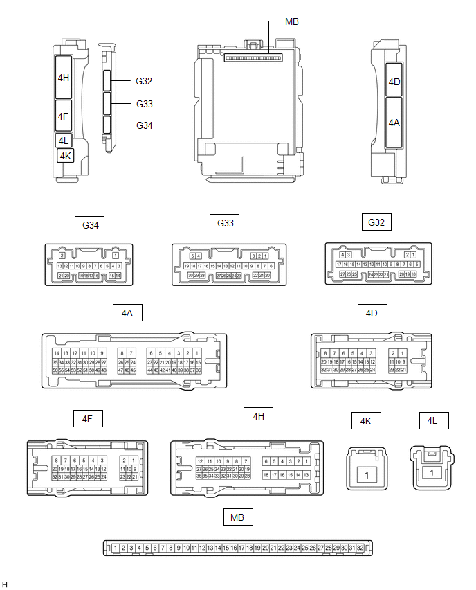
(a) Remove the main body ECU (multiplex network body ECU) from the instrument panel junction block assembly.
Click here 
(b) Measure the resistance according to the value(s) in the table below.
HINT:
Measure the values on the wire harness side with the connectors connected.
|
Terminal No. (Symbol) | Wiring Color |
Input/Output | Terminal Description |
Condition | Specified Condition |
Related Data List Item |
|
G32-19 (GND2) - Body ground |
W-B - Body ground | - |
Ground | Always |
Below 1 ╬® | - |
(c) Reconnect the instrument panel junction block assembly connectors.
(d) Measure the resistance and voltage according to the value(s) in the table below.
HINT:
Measure the values on the wire harness side with the connector disconnected.
|
Terminal No. (Symbol) | Wiring Color |
Input/Output | Terminal Description |
Condition | Specified Condition |
Related Data List Item |
|
MB-31 (BECU) - Body ground |
- | Input |
Battery power supply |
Always | 11 to 14 V |
- |
|
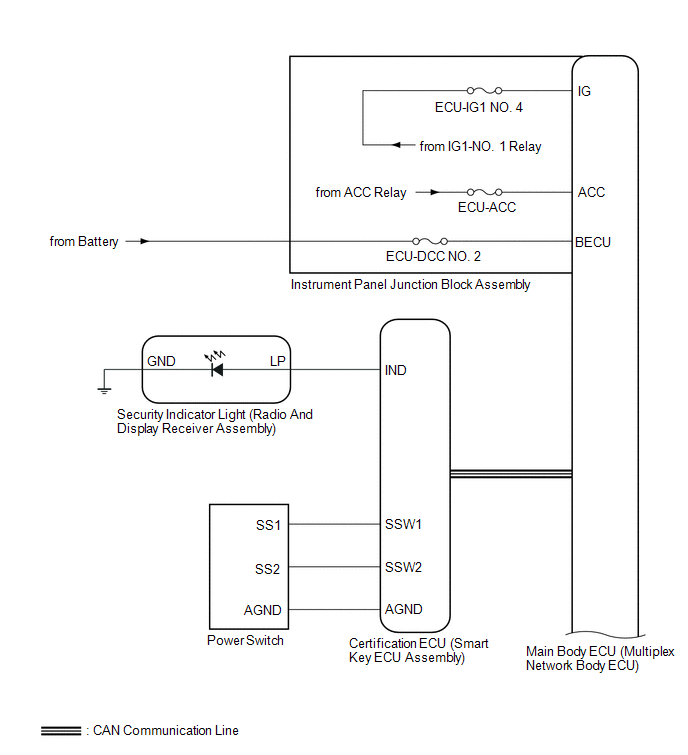
MB-32 (IG) - Body ground |
- | Input |
Ignition power supply (IG signal) |
Engine switch off | Below 1 V |
IG SW |
| Engine switch on (IG) |
11 to 14 V |
|
MB-30 (ACC) - Body ground |
- | Input |
Ignition power supply (ACC signal) |
Engine switch off | Below 1 V |
ACC SW |
| Engine switch on (IG) |
11 to 14 V |
|
MB-11 (GND1) - Body ground |
- | - |
Ground | Always |
Below 1 ╬® | - |
|
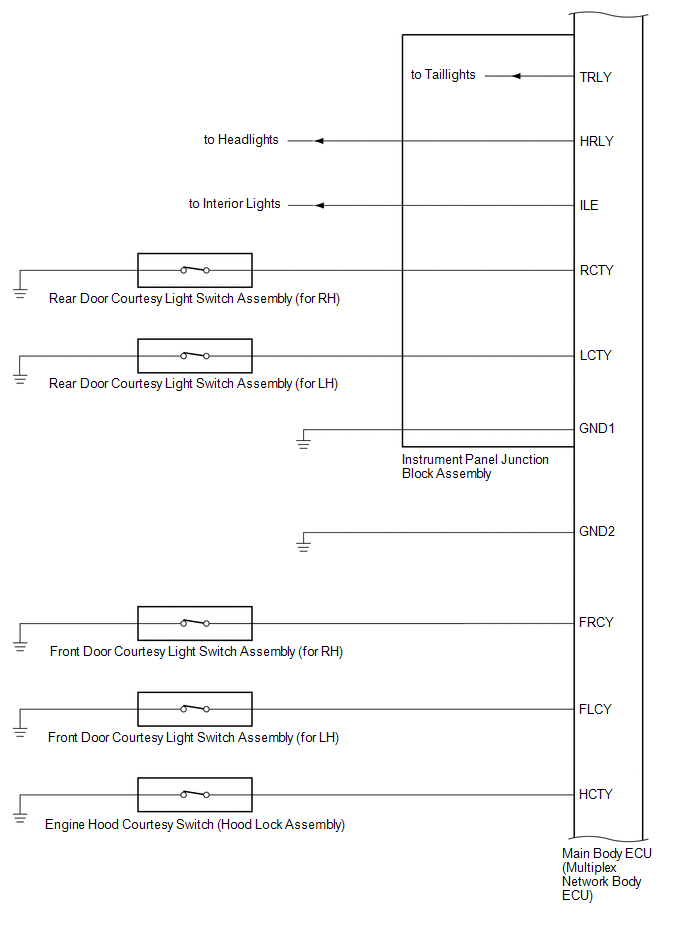
G33-1 (FLCY) - Body ground |
W - Body ground |
Input | Front door courtesy light switch assembly (for LH) input |
Front door LH closed |
10 k╬® or higher |
FL Door Courtesy SW |
|
Front door LH open | Below 1 ╬® |
|
G33-6 (FRCY) - Body ground |
BE - Body ground |
Input | Front door courtesy light switch assembly (for RH) input |
Front door RH closed |
10 k╬® or higher |
FR Door Courtesy SW |
|
Front door RH open | Below 1 ╬® |
|
MB-13 (LCTY) - Body ground |
- | Input |
Rear door courtesy light switch assembly (for LH) input |
Rear door LH closed | 10 k╬® or higher |
RL Door Courtesy SW |
|
Rear door LH open | Below 1 ╬® |
|
MB-2 (RCTY) - Body ground |
- | Input |
Rear door courtesy light switch assembly (for RH) input |
Rear door RH closed | 10 k╬® or higher |
RR Door Courtesy SW |
|
Rear door RH open | Below 1 ╬® |
|
G33-30 (HCTY) - Body ground |
GR - Body ground |
Input | Engine hood courtesy switch input |
Engine hood open | 10 k╬® or higher |
Hood Courtesy SW |
|
Engine hood closed | Below 1 ╬® |
|
MB-4 (LGCY) - Body ground |
- | Input |
Luggage compartment door courtesy light switch input |
Luggage compartment door closed |
10 k╬® or higher |
Luggage Courtesy SW |
|
Luggage compartment door open |
Below 1 ╬® |
|
MB-14 (TRLY) - Body ground |
- | Output |
Taillight relay drive output |
Always | 11 to 14 V |
- |
(e) Install the main body ECU (multiplex network body ECU) to instrument panel junction block assembly.
Click here
(f) Measure the voltage and check for pulses according to the value(s) in the table below.
|
Terminal No. (Symbol) | Wiring Color |
Input/Output | Terminal Description |
Condition | Specified Condition |
Related Data List Item |
|
4D-13 (LSFL) - Body ground |
W - Body ground |
Input | Front door LH unlock detection switch input |
Front door LH unlocked |
Below 1 V |
FL Door Lock Pos SW |
|
Front door LH locked |
11 to 14 V |
|
4D-12 (LSFR) - Body ground |
GR - Body ground |
Input | Front door RH unlock detection switch input |
Front door RH unlocked |
Below 1 V |
FR Door Lock Pos SW |
|
Front door RH locked |
11 to 14 V |
|
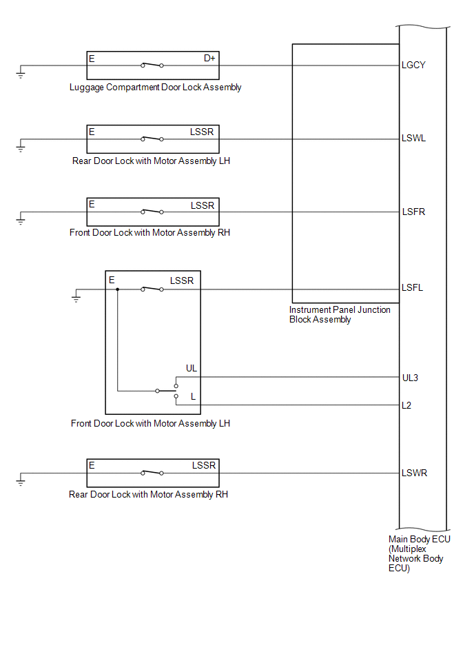
G34-18 (L2) - Body ground |
LG - Body ground |
Input | Driver door key-linked lock input |
Driver door key cylinder turned to lock position |
Below 1 V |
Door Key SW-Lock |
|
Driver door key cylinder off |
11 to 14 V |
|
G34-17 (UL3) - Body ground |
BE - Body ground |
Input | Driver door key-linked unlock input |
Driver door key cylinder turned to unlock position |
Below 1 V |
D Door Key SW-UL |
|
Driver door key cylinder off |
11 to 14 V |
|
4D-14 (LSWL) - Body ground |
GR - Body ground |
Input | Rear door LH unlock detection switch input |
Rear door LH unlocked |
Below 1 V |
RL-Door Lock Pos SW |
|
Rear door LH locked | 11 to 14 V |
|
G32-20 (LSWR) - Body ground |
L - Body ground |
Input | Rear door RH unlock detection switch input |
Rear door RH unlocked |
Below 1 V |
RR-Door Lock Pos SW |
|
Rear door RH locked | 11 to 14 V |
|
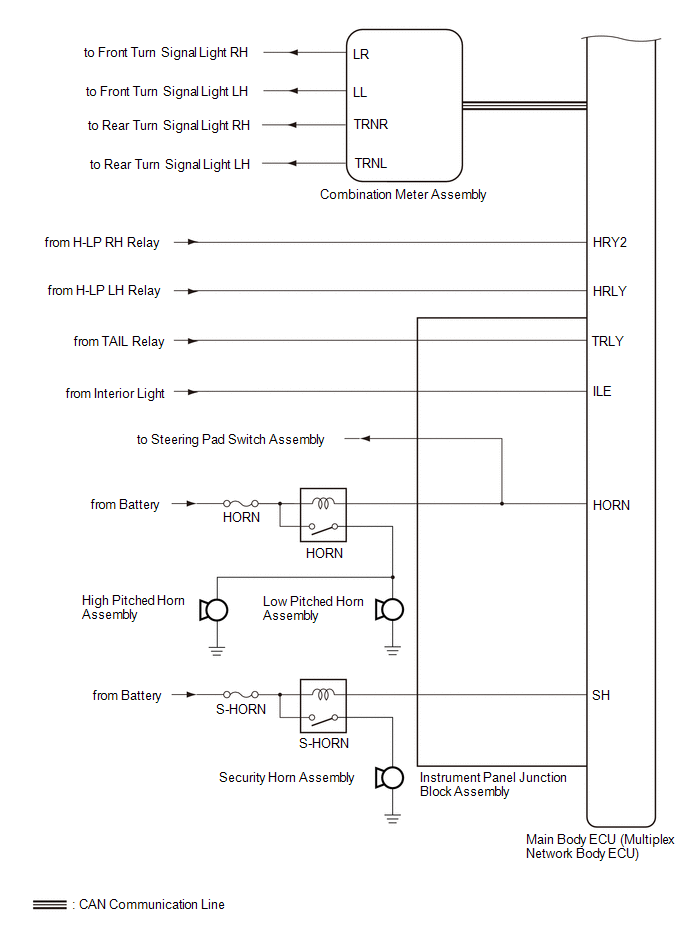
4A-20 (SH) - Body ground |
L - Body ground | Output |
Security horn assembly drive |
Security horn assembly sounding (Theft deterrent system in alarm sounding state) |
Pulse generation (Below 1 V ŌåÉ ŌåÆ 11 to 14 V) |
- |
| 4F-27 (HORN) - Body ground |
W - Body ground | Output |
Vehicle horns drive | Vehicle horns sounding
(Theft deterrent system in alarm sounding state) |
Pulse generation (Below 1 V ŌåÉ ŌåÆ 11 to 14 V) |
- |
| 4F-31 (HRLY) - Body ground |
V - Body ground | Input |
H-LP LH relay drive output |
Low beams blinking (Theft deterrent system in alarm sounding state) |
Pulse generation (Below 1 V ŌåÉ ŌåÆ 11 to 14 V) |
- |
| G33-12 (HRY2) - Body ground |
BE - Body ground | Input |
H-LP RH relay drive output |
Low beams blinking (Theft deterrent system in alarm sounding state) |
Pulse generation (Below 1 V ŌåÉ ŌåÆ 11 to 14 V) |
- |
| 4D-29 (ILE) - Body ground |
LA-G - Body ground | Output |
Interior lights drive output |
Interior lights illuminated (Theft deterrent system in alarm sounding state) |
Below 1 V | - |