Components
COMPONENTS
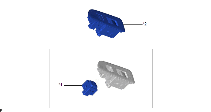
ILLUSTRATION
|
*1 | DOOR CONTROL SWITCH ASSEMBLY |
*2 | POWER WINDOW REGULATOR SWITCH ASSEMBLY WITH FRONT DOOR UPPER ARMREST BASE PANEL |
Inspection
INSPECTION
PROCEDURE
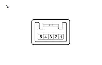
1. INSPECT DOOR CONTROL SWITCH ASSEMBLY
| (a) Measure the resistance according to the value(s) in the table below. Standard Resistance:
If the result is not as specified, replace the door control switch assembly. |
|
Installation
INSTALLATION
PROCEDURE
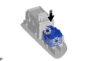
1. INSTALL DOOR CONTROL SWITCH ASSEMBLY
(a) Engage the 2 claws to install the door control switch assembly as shown in the illustration.
 |
Install in this Direction |
2. INSTALL POWER WINDOW REGULATOR SWITCH ASSEMBLY WITH FRONT DOOR UPPER ARMREST BASE PANEL
Click here 
Removal
REMOVAL
PROCEDURE
1. REMOVE POWER WINDOW REGULATOR SWITCH ASSEMBLY WITH FRONT DOOR UPPER ARMREST BASE PANEL
Click here 
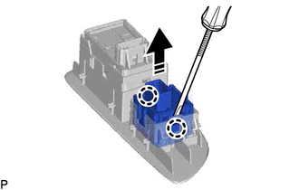
2. REMOVE DOOR CONTROL SWITCH ASSEMBLY
(a) Using a screwdriver, disengage the 2 claws and remove the door control switch assembly as shown in the illustration.
 |
Remove in this Direction |
Toyota Avalon (XX50) 2019-2022 Service & Repair Manual > Sfi System: Drive Start Control
DESCRIPTION The drive start control is controlled by the ECM. If the ECM determines that the shift lever and accelerator pedal are operated abnormally, driving force is restricted and, when necessary, a warning is displayed on the combination meter assembly. CAUTION / NOTICE / HINT HINT: Even if the ...