Components
COMPONENTS
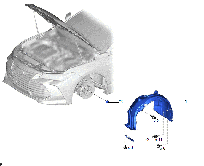
ILLUSTRATION
|
*1 | FRONT FENDER SPLASH SHIELD SUB-ASSEMBLY LH |
*2 | FRONT WHEEL OPENING EXTENSION PAD LH |
|
*3 | WIRELESS DOOR LOCK BUZZER |
- | - |
Installation
INSTALLATION
PROCEDURE
1. INSTALL WIRELESS DOOR LOCK BUZZER
(a) Engage the clamp to install the wireless door lock buzzer.
(b) Connect the connector.
2. INSTALL FRONT FENDER SPLASH SHIELD SUB-ASSEMBLY LH
HINT:
Use the same procedure as for the RH side.
Click here

3. INSTALL FRONT WHEEL OPENING EXTENSION PAD LH
HINT:
Use the same procedure as for the RH side.
Click here
4. INSTALL FRONT WHEEL LH
Click here
Removal
REMOVAL
PROCEDURE
1. REMOVE FRONT WHEEL LH
Click here 
2. REMOVE FRONT WHEEL OPENING EXTENSION PAD LH
HINT:
Use the same procedure as for the RH side.
Click here
3. REMOVE FRONT FENDER SPLASH SHIELD SUB-ASSEMBLY LH
HINT:
Use the same procedure as for the RH side.
Click here
4. REMOVE WIRELESS DOOR LOCK BUZZER
| (a) Disconnect the connector. |
|
(b) Disengage the clamp to remove the wireless door lock buzzer.
Toyota Avalon (XX50) 2019-2022 Owners Manual > Other interior features: Garage door opener
The garage door opener can be programmed to operate garage doors, gates, entry doors, door locks, home lighting systems, security systems, and other devices. HomeLink The HomeLink wireless control system in your vehicle has 3 buttons which can be programmed to operate 3 different devices. Refer to ...


