Toyota Avalon (XX50): Ambient Temperature Sensor(for A25a-fxs)
Components
COMPONENTS
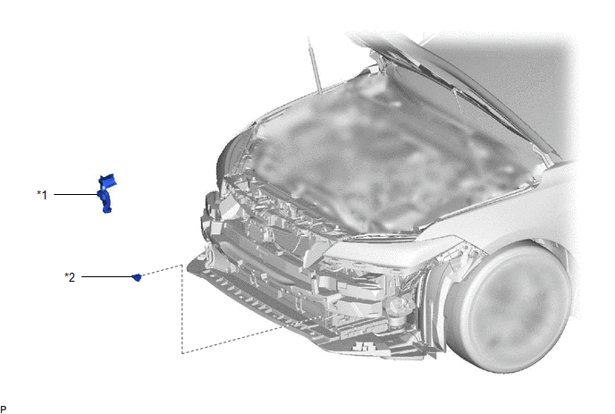
ILLUSTRATION

|
*1 | FRONT RADIATOR SIDE AIR GUIDE PLATE LH |
*2 | THERMISTOR ASSEMBLY |
Inspection
INSPECTION
PROCEDURE
1. INSPECT THERMISTOR ASSEMBLY
| (a) Measure the resistance according to the value(s) in the table below.
Standard Resistance: |
Tester Connection | Condition |
Specified Condition | |
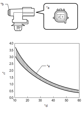
1 - 2 | 10°C (50°F) |
3.00 to 3.73 kΩ | |
15°C (59°F) | 2.45 to 2.88 kΩ | |
20°C (68°F) | 1.95 to 2.30 kΩ | |
25°C (77°F) | 1.60 to 1.80 kΩ | |
30°C (86°F) | 1.28 to 1.47 kΩ | |
35°C (95°F) | 1.00 to 1.22 kΩ | |
40°C (104°F) | 0.80 to 1.00 kΩ | |
45°C (113°F) | 0.65 to 0.85 kΩ | |
50°C (122°F) | 0.50 to 0.70 kΩ | |
55°C (131°F) | 0.44 to 0.60 kΩ | |
60°C (140°F) | 0.36 to 0.50 kΩ |
NOTICE:
- Hold the sensor only by its connector. Touching the sensing portion may change the resistance value.
- When measuring, the sensor temperature must be the same as the ambient temperature.
HINT: As the temperature increases, the resistance decreases (see the graph).
If the result is not as specified, replace the thermistor assembly. |
 |
|
*a | Component without harness connected
(Thermistor Assembly) | |
*b | Sensing Portion | |
*c | Resistance (kΩ) | |
*d | Temperature (°C (°F)) | |
*e | Allowable Range | | |
Installation
INSTALLATION
PROCEDURE
1. INSTALL THERMISTOR ASSEMBLY
(a) Connect the connector.
(b) Engage the clamp to install the thermistor assembly.
2. INSTALL FRONT RADIATOR SIDE AIR GUIDE PLATE LH
(a) Engage the 2 claws to install the front radiator side air guide plate LH.
3. INSTALL FRONT BUMPER ASSEMBLY
Click here

Removal
REMOVAL
CAUTION / NOTICE / HINT
The
necessary procedures (adjustment, calibration, initialization, or
registration) that must be performed after parts are removed and
installed, or replaced during thermistor assembly removal/installation
are shown below.
Necessary Procedure After Parts Removed/Installed/Replaced |
Replaced Part or Performed Procedure |
Necessary Procedure | Effect/Inoperative Function when Necessary Procedure not Performed |
Link |
|
*: Applies only for when removing and installing or replacing the television camera assembly.
|
| Front television camera assembly, front bumper assembly or radiator grille |
- Television camera view adjustment
- Television camera assembly optical axis adjustment (Back camera position setting)*
| Panoramic View Monitor System |
 for Initialization for Initialization
 for Calibration for Calibration |
|
Front bumper assembly |
- Measurement of ultrasonic sensor detection angle
- Ultrasonic sensor detection angle registration
|
- Intelligent Clearance Sonar System
- Intuitive Parking Assist System
|
 |
PROCEDURE
1. REMOVE FRONT BUMPER ASSEMBLY
Click here

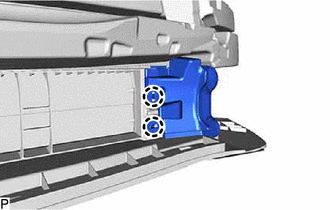
2. REMOVE FRONT RADIATOR SIDE AIR GUIDE PLATE LH
| (a) Disengage the 2 claws to remove the front radiator side air guide plate LH. |
|
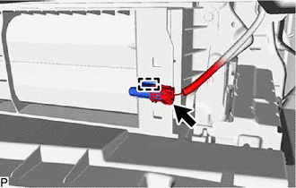
3. REMOVE THERMISTOR ASSEMBLY
(b) Disconnect the connector to remove the thermistor assembly.


 for Initialization
 for Calibration


