Components
COMPONENTS
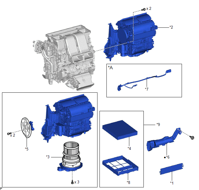
ILLUSTRATION
|
*A | w/ PTC Heater |
- | - |
|
*1 | AIR FILTER COVER PLATE |
*2 | BLOWER ASSEMBLY |
|
*3 | BLOWER MOTOR WITH FAN SUB-ASSEMBLY |
*4 | CLEAN AIR FILTER |
|
*5 | NO. 1 BLOWER DAMPER SERVO SUB-ASSEMBLY |
*6 | NO. 2 AIR DUCT |
|
*7 | NO. 2 INSTRUMENT PANEL WIRE |
*8 | AIR FILTER CASE |
|
*9 | AIR FILTER SUB-ASSEMBLY |
- | - |
|
в—Џ | Non-reusable part |
- | - |
Disassembly
DISASSEMBLY
PROCEDURE
1. REMOVE AIR FILTER COVER PLATE
(a) Disengage the claw and 2 guides as shown in the illustration to remove the air filter cover plate.
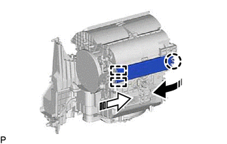
 | Remove in this Direction (1) |
 |
Remove in this Direction (2) |
2. REMOVE CLEAN AIR FILTER
(a) Remove the air filter sub-assembly as shown in the illustration.
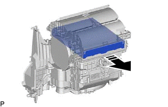
 |
Remove in this Direction |
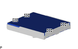
| (b) Disengage the 4 guides to remove the clean air filter from the air filter case. |
|
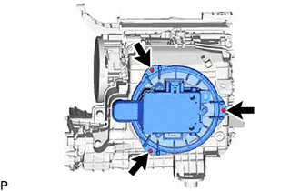
3. REMOVE BLOWER MOTOR WITH FAN SUB-ASSEMBLY
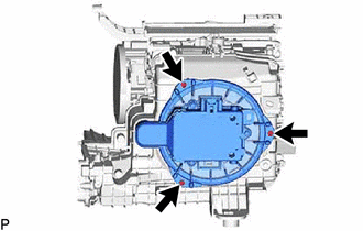
| (a) Remove the 3 screws and blower motor with fan sub-assembly. |
|
4. REMOVE NO. 1 BLOWER DAMPER SERVO SUB-ASSEMBLY
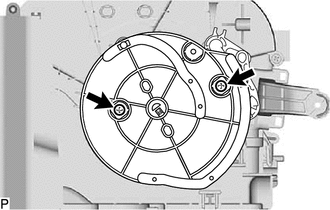
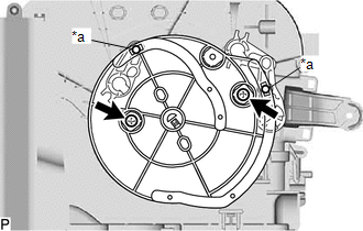
| (a) Remove the 2 screws and No. 1 blower damper servo sub-assembly. |
|
Installation
INSTALLATION
PROCEDURE
1. INSTALL BLOWER ASSEMBLY
(a) Engage the 2 guides and 2 claws.
(b) Install the blower assembly to the air conditioning radiator assembly with the 2 screws.
(c) Engage each guide.
(d) Connect the connector.
2. INSTALL NO. 2 AIR DUCT
Click here 
3. INSTALL NO. 2 INSTRUMENT PANEL WIRE (w/ PTC Heater)
Click here 
4. INSTALL AIR CONDITIONER UNIT ASSEMBLY
for A25A-FXS:
Click here 
for 2GR-FKS:
Click here 
Reassembly
REASSEMBLY
PROCEDURE
1. INSTALL NO. 1 BLOWER DAMPER SERVO SUB-ASSEMBLY
| (a)
Connect the 2 links of the blower assembly to the 2 grooves on the
plate of the No. 1 blower damper servo sub-assembly as shown in the
illustration. | |
(b) Install the No. 1 blower damper servo sub-assembly with the 2 screws.
2. INSTALL BLOWER MOTOR WITH FAN SUB-ASSEMBLY
| (a) Install the blower motor with fan sub-assembly with the 3 screws.
NOTICE: Replace the blower motor with fan sub-assembly if it has been dropped or subjected to a severe impact. |
|
3. INSTALL CLEAN AIR FILTER
(a)
Engage the 2 guides on the cutout side of the air filter case and then
engage the 2 guides as shown in the illustration to install the clean
air filter.
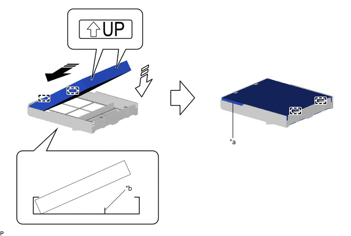
|
*a | Cutout |
*b | Rib |
 |
Install in this Direction (1) |
 |
Install in this Direction (2) |
NOTICE:
- Make sure that the "UP" marks are facing the correct direction before installing the clean air filter.
- Make sure that there is no clearance between the clean air filter and
air filter case and that the clean air filter is not deformed.
(b) Install the air filter sub-assembly as shown in the illustration.
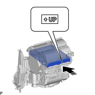
 | Install in this Direction |
NOTICE:
Make sure that the "UP" mark is facing the correct direction before installing the air filter sub-assembly.
4. INSTALL AIR FILTER COVER PLATE
(a) Engage the 2 guides and claw as shown in the illustration to install the air filter cover plate.
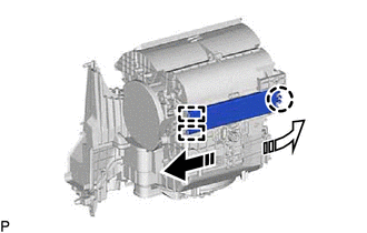
 | Install in this Direction (1) |
 |
Install in this Direction (2) |
Removal
REMOVAL
CAUTION / NOTICE / HINT
The
necessary procedures (adjustment, calibration, initialization or
registration) that must be performed after parts are removed and
installed, or replaced during blower unit removal/installation are shown
below.
Necessary Procedure After Parts Removed/Installed/Replaced (for Gasoline Model) |
Replaced Part or Performed Procedure |
Necessary Procedure | Effect/Inoperative Function when Necessary Procedure not Performed |
Link |
|
*: When performing learning using the Techstream.
Click here  |
|
Disconnect cable from negative battery terminal |
Perform steering sensor zero point calibration |
Lane Departure Alert System (w/ Steering Control) |
 |
|
Pre-collision System |
|
Intelligent Clearance Sonar System* |
|
Lighting System (for Gasoline Model with Cornering Light) |
|
Memorize steering angle neutral point |
Parking Assist Monitor System |
 |
|
Panoramic View Monitor System |
 |
|
Steering sensor | Steering angle zero point learning (Initialize intelligent clearance sonar system) |
- Intelligent Clearance Sonar System
- Intuitive Parking Assist System
|
 |
- Steering angle neutral point (Initialize parking assist monitor system)
- Steering angle setting
| Parking Assist Monitor System |
 for Initialization for Initialization
 for Calibration for Calibration |
|
Steering angle zero point learning (Initialize panoramic view monitor system) |
Panoramic View Monitor System |
 for Initialization for Initialization
 for Calibration for Calibration |
|
Front passenger seat | Zero point calibration (Occupant classification system) |
- Occupant classification system
- Passenger airbag ON/OFF indicator
- Airbag system (Front passenger side)
- Seat belt warning system (Front passenger)
|
 |
CAUTION:
Some
of these service operations affect the SRS airbag system. Read the
precautionary notices concerning the SRS airbag system before servicing.
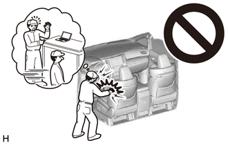
Click here

HINT:
Before removing the blower assembly, set the air conditioning to recirculation mode.
Necessary Procedure After Parts Removed/Installed/Replaced (for HV Model) |
Replaced Part or Performed Procedure |
Necessary Procedure | Effect/Inoperative Function When Necessary Procedures are not Performed |
Link |
|
*: When performing learning using the Techstream.
Click here  |
|
Disconnect cable from negative auxiliary battery terminal |
Perform steering sensor zero point calibration |
Lane Departure Alert System (w/ Steering Control) |
 |
|
Pre-collision System |
|
Intelligent Clearance Sonar System* |
|
Lighting System (for HV Model with Cornering Light) |
|
Memorize steering angle neutral point |
Parking Assist Monitor System |
 |
|
Panoramic View Monitor System |
 |
|
Steering sensor | Steering angle zero point learning (Initialize intelligent clearance sonar system) |
- Intelligent Clearance Sonar System
- Intuitive Parking Assist System
|
 |
- Steering angle zero point learning (Initialize parking assist monitor system)
- Steering angle setting
| Parking Assist Monitor System |
 for Initialization for Initialization
 for Calibration for Calibration |
|
Steering angle zero point learning (Initialize panoramic view monitor system) |
Panoramic View Monitor System |
 for Initialization for Initialization
 for Calibration for Calibration |
|
Front passenger seat | Zero point calibration (Occupant classification system) |
- Occupant classification system
- Passenger airbag ON/OFF indicator
- Airbag system (Front passenger side)
- Seat belt warning system (Front passenger)
|
 |
CAUTION:
Some
of these service operations affect the SRS airbag system. Read the
precautionary notices concerning the SRS airbag system before servicing.

Click here

HINT:
Before removing the blower assembly, set the air conditioning to recirculation mode.
PROCEDURE
1. REMOVE AIR CONDITIONER UNIT ASSEMBLY
for A25A-FXS:
Click here

for 2GR-FKS:
Click here

2. REMOVE NO. 2 INSTRUMENT PANEL WIRE (w/ PTC Heater)
Click here 
3. REMOVE NO. 2 AIR DUCT
Click here 
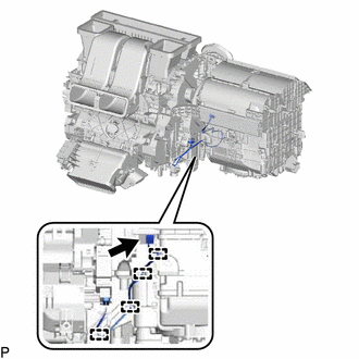
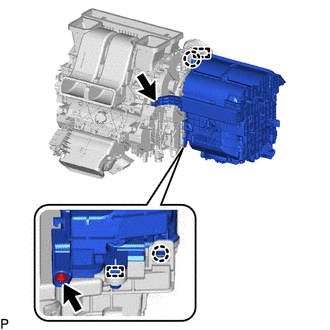
4. REMOVE BLOWER ASSEMBLY
| (a) Disconnect the connector. | |
(b) Disengage each guide.
(d) Disengage the 2 claws and 2 guides and remove the blower assembly from the air conditioning radiator assembly.






 for Initialization
 for Calibration
 for Initialization
 for Calibration


 for Initialization
 for Calibration
 for Initialization
 for Calibration


