Installation
INSTALLATION
PROCEDURE
1. ADJUST COMPRESSOR OIL
| (a)
When replacing the compressor with motor assembly with a new one,
gradually discharge the inert gas from the service valve, and drain the
following amount of oil from the new compressor with motor assembly
before installation. Standard: (Oil
capacity inside the new compressor with motor assembly: 120 to 135 cc
(4.06 to 4.56 fl. oz)) - (Remaining oil amount in the removed compressor
with motor assembly) = (Oil amount to be removed from the new
compressor)
NOTICE:
- If a new compressor with motor assembly is installed without removing
some oil, there will be too much oil in the system due to the oil
remaining in the pipes of the vehicle. Excessive oil in the system
prevents heat exchange in the refrigeration cycle and causes ineffective
cooling.
- If the amount of oil remaining in the old compressor with motor assembly
is too small, check the air conditioning system for oil leaks.
- Be sure to use ND-OIL 11 or equivalent compressor oil. If any compressor
oil other than ND-OIL 11 is used, compressor with motor assembly
insulation performance may decrease, resulting in leakage of electric
power.
| |
2. INSTALL COMPRESSOR WITH MOTOR ASSEMBLY
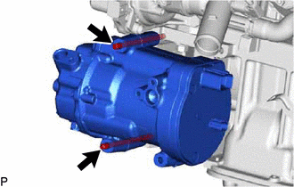
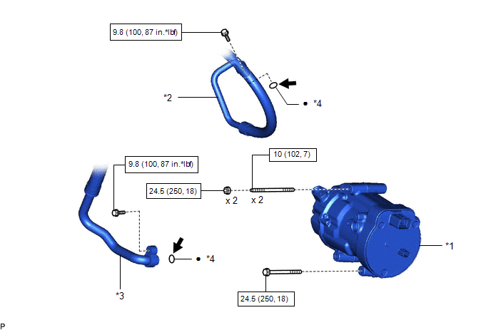
(a) Using an E8 "TORX" socket wrench, temporarily install the compressor with motor assembly with the 2 stud bolts.
Torque:
10 N·m {102 kgf·cm, 7 ft·lbf}
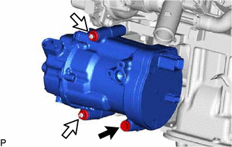
(b) Install the compressor with motor assembly with the bolt and 2 nuts.
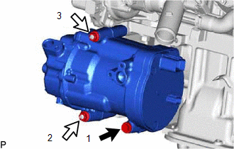
 | Bolt |
 |
Nut |
Torque:
24.5 N·m {250 kgf·cm, 18 ft·lbf}
HINT:
Tighten the bolt and nuts in the order shown in the illustration.
(c) Connect the connector (B).
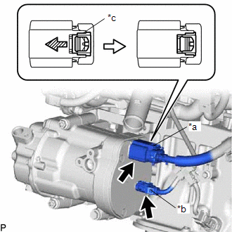
|
*a | Connector (A) |
|
*b | Connector (B) |
|
*c | Green-colored Lock |
 | Slide |
(d) Remove the insulating tape from the connector (A).
(e) Connect the connector (A) and slide the green-colored lock as shown in the illustration to securely lock it.
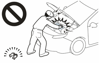
CAUTION:
Make sure to wear insulated gloves.
NOTICE:
Make sure that the connector is connected securely.
3. CONNECT NO. 1 COOLER REFRIGERANT DISCHARGE HOSE SUB-ASSEMBLY
(a) Remove the vinyl tape from the No. 1 cooler refrigerant discharge hose sub-assembly.
(b) Sufficiently apply compressor oil to a new O-ring and the fitting surface of the compressor with motor assembly.
Compressor Oil:
ND-OIL 11 or equivalent
(c) Install the O-ring to the No. 1 cooler refrigerant discharge hose sub-assembly.
NOTICE:
Keep the O-ring and O-ring fitting surface free of foreign matter.
(d) Connect the No. 1 cooler refrigerant discharge hose sub-assembly to the compressor with motor assembly with the bolt.
Torque:
9.8 N·m {100 kgf·cm, 87 in·lbf}
4. CONNECT SUCTION HOSE SUB-ASSEMBLY
(a) Remove the vinyl tape from the suction hose sub-assembly.
(b) Sufficiently apply compressor oil to a new O-ring and the fitting surface of the compressor with motor assembly.
Compressor Oil:
ND-OIL 11 or equivalent
(c) Install the O-ring to the suction hose sub-assembly.
NOTICE:
Keep the O-ring and O-ring fitting surface free of foreign matter.
(d) Connect the suction hose sub-assembly to the compressor with motor assembly with the bolt.
Torque:
9.8 N·m {100 kgf·cm, 87 in·lbf}
5. INSTALL RADIATOR ASSEMBLY
Click here 
6. INSTALL SERVICE PLUG GRIP
Click here 
7. CHARGE AIR CONDITIONING SYSTEM WITH REFRIGERANT
Click here 
8. WARM UP COMPRESSOR
Click here 
9. INSPECT FOR REFRIGERANT LEAK
Click here 
Removal
REMOVAL
CAUTION / NOTICE / HINT
The
necessary procedures (adjustment, calibration, initialization or
registration) that must be performed after parts are removed and
installed, or replaced during compressor with motor assembly
removal/installation are shown below.
Necessary Procedure After Parts Removed/Installed/Replaced |
Replaced Part or Performed Procedure |
Necessary Procedures | Effect/Inoperative Function when Necessary Procedure not Performed |
Link |
|
*1: When performing learning using the Techstream.
Click here  *2: Applies only for when removing and installing or replacing the television camera assembly. |
|
Disconnect cable from negative auxiliary battery terminal |
Perform steering sensor zero point calibration |
Lane departure alert system (w/ Steering Control) |
 |
|
Pre-collision system |
| Intelligent clearance sonar system*1 |
|
Lighting system (for Gasoline Model with Cornering Light) |
|
Memorize steering angle neutral point |
Parking assist monitor system |
 |
|
Panoramic view monitor system |
 |
|
Front television camera assembly, front bumper assembly or radiator grille |
- Television camera view adjustment
- Television camera assembly optical axis adjustment (Back camera position setting)*2
| Panoramic view monitor system |
 for Initialization for Initialization
 for Calibration for Calibration |
|
Front bumper assembly |
- Measurement of ultrasonic sensor detection angle
- Ultrasonic sensor detection angle registration
|
- Intelligent clearance sonar system
- Intuitive parking assist system
|
 |
- Headlight assembly
- Headlight ECU sub-assembly
| Synchronize the vehicle information |
Lighting system (for HV Model with Cornering Light) |
 |
- Swing grill actuator assembly
- Radiator shutter sub-assembly
| Change grille shutter control mode and/or perform initialization |
Grille Shutter System |
 |
CAUTION:
NOTICE:
After
turning the power switch off, waiting time may be required before
disconnecting the cable from the negative (-) auxiliary battery
terminal. Therefore, make sure to read the disconnecting the cable from
the negative (-) auxiliary battery terminal notices before proceeding
with work.
Click here 
PROCEDURE
1. RECOVER REFRIGERANT FROM REFRIGERATION SYSTEM
Click here

2. REMOVE SERVICE PLUG GRIP
Click here

3. CHECK TERMINAL VOLTAGE
(a) Disconnect the engine room main wire.
Click here 
(b) Remove the connector cover assembly.
Click here 
(c) Check the terminal voltage.
Click here 
(d) Install the connector cover assembly.
Click here 
(e) Connect the engine room main wire.
Click here 
4. REMOVE RADIATOR ASSEMBLY
Click here 
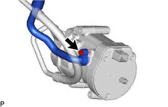
5. DISCONNECT SUCTION HOSE SUB-ASSEMBLY
| (a) Remove the bolt and disconnect the suction hose sub-assembly from the compressor with motor assembly. |
|
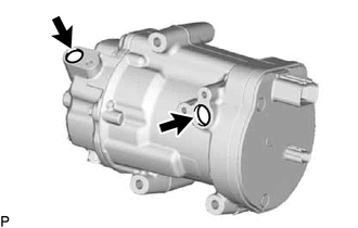
(b) Remove the O-ring from the suction hose sub-assembly.
NOTICE:
Seal the openings of the disconnected parts using vinyl tape to prevent moisture and foreign matter from entering them.
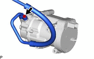
6. DISCONNECT NO. 1 COOLER REFRIGERANT DISCHARGE HOSE SUB-ASSEMBLY
| (a)
Remove the bolt and disconnect the No. 1 cooler refrigerant discharge
hose sub-assembly from the compressor with motor assembly. | |
(b) Remove the O-ring from the No. 1 cooler refrigerant discharge hose sub-assembly.
NOTICE:
Seal the openings of the disconnected parts using vinyl tape to prevent moisture and foreign matter from entering them.
7. REMOVE COMPRESSOR WITH MOTOR ASSEMBLY
(a)
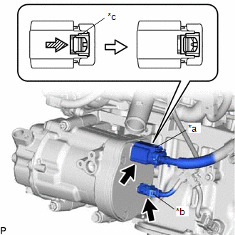
Using a screwdriver, slide the green-colored lock of the connector (A)
as shown in the illustration to release it and disconnect the connector.
|
*a | Connector (A) |
|
*b | Connector (B) |
|
*c | Green-colored Lock |
 |
Slide |
CAUTION:
Make sure to wear insulated gloves.
NOTICE:
Insulate the disconnected terminals and connector with insulating tape.
(b) Disconnect the connector (B).
(c) Remove the bolt and 2 nuts.
 |
Bolt |
 |
Nut |
| (d) Using an E8 "TORX" socket wrench, remove the 2 stud bolts and compressor with motor assembly. |
|




 for Initialization
 for Calibration


