Installation
INSTALLATION
PROCEDURE
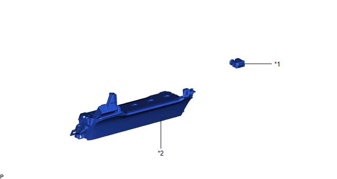
1. INSTALL COOLER (ROOM TEMP. SENSOR) THERMISTOR
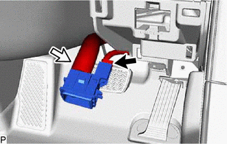
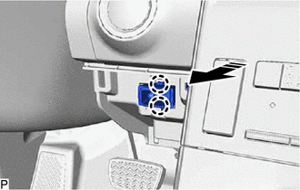
(a) Connect the connector and aspirator.
(b) Engage the 2 claws to install the cooler (room temp. sensor) thermistor as shown in the illustration.
 |
Install in this Direction |
2. INSTALL LOWER NO. 1 INSTRUMENT PANEL AIRBAG ASSEMBLY
Click here 
Removal
REMOVAL
CAUTION / NOTICE / HINT
The
necessary procedures (adjustment, calibration, initialization, or
registration) that must be performed after parts are removed and
installed, or replaced during cooler (room temp. sensor) thermistor
removal/installation are shown below.
Necessary Procedure After Parts Removed/Installed/Replaced (for Gasoline Model) |
Replaced Part or Performed Procedure |
Necessary Procedure | Effect/Inoperative Function when Necessary Procedure not Performed |
Link |
|
*: When performing learning using the Techstream.
Click here  |
|
Disconnect cable from negative battery terminal |
Perform steering sensor zero point calibration |
Lane departure alert system (w/ Steering Control) |
|
|
Pre-collision system |
|
Intelligent clearance sonar system* |
|
Lighting system (for Gasoline Model with Cornering Light) |
|
Memorize steering angle neutral point |
Parking assist monitor system |
|
|
Panoramic view monitor system |
|
CAUTION:
Some
of these service operations affect the SRS airbag system. Read the
precautionary notices concerning the SRS airbag system before servicing.
Click here
 Necessary Procedure After Parts Removed/Installed/Replaced (for HV Model)
 |
Replaced Part or Performed Procedure |
Necessary Procedure | Effect/Inoperative Function When Necessary Procedures are not Performed |
Link |
|
*: When performing learning using the Techstream.
Click here |
|
Disconnect cable from negative auxiliary battery terminal |
Perform steering sensor zero point calibration |
Lane departure alert system (w/ Steering Control) |
|
|
Pre-collision system |
|
Intelligent clearance sonar system* |
|
Lighting system (for HV Model with Cornering Light) |
|
Memorize steering angle neutral point |
Parking assist monitor system |
|
|
Panoramic view monitor system |
|
CAUTION:
Some
of these service operations affect the SRS airbag system. Read the
precautionary notices concerning the SRS airbag system before servicing.
Click here
PROCEDURE
1. REMOVE LOWER NO. 1 INSTRUMENT PANEL AIRBAG ASSEMBLY
Click here
2. REMOVE COOLER (ROOM TEMP. SENSOR) THERMISTOR
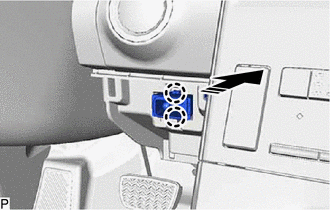
 | Remove in this Direction |
(a) Disengage the 2 claws as shown in the illustration.
| (b) Disconnect the connector and aspirator to remove the cooler (room temp. sensor) thermistor. |
|