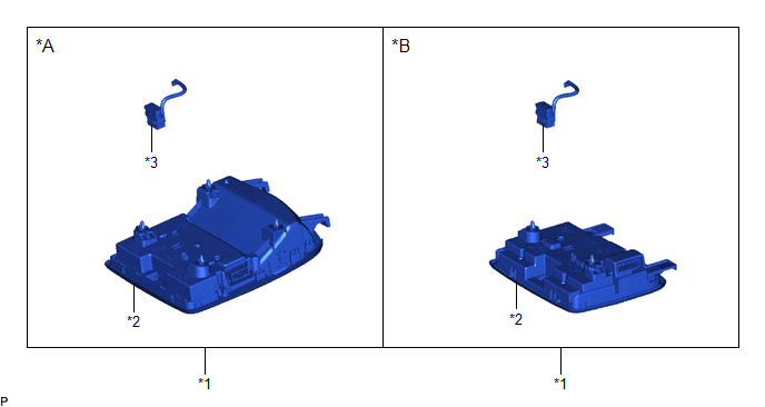
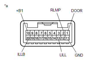
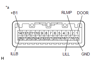
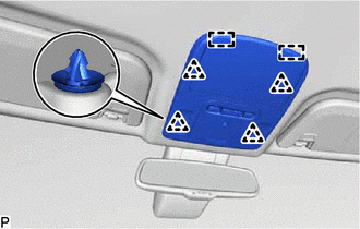
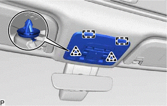
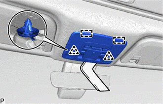
COMPONENTS ILLUSTRATION *A for Normal Roof *B for Moon Roof *1 ROOF CONSOLE BOX ASSEMBLY *2 ROOF CONSOLE BOX SUB-ASSEMBLY *3 TELEPHONE MICROPHONE ASSEMBLY - - INSPECTION PROCEDURE 1. INSPECT ROOF CONSOLE BOX SUB-ASSEMBLY (for Normal Roof) (a) Apply auxiliary battery voltage to the roof console box sub-assembly and check that the lights illuminate. OK: Measurement Condition Condition Specified Condition Auxiliary battery positive (+) → 10 (+B1) Auxiliary battery negative (-) → 11 (GND) Dome light switch off and map light switch LH on Map light LH illuminates Dome light switch off and map light switch RH on Map light RH illuminates Map light switch LH and RH off and dome light switch on Map light LH and RH illuminate Auxiliary battery positive (+) → 10 (+B1) Auxiliary battery negative (-) → 1 (DOOR) Map light switch LH and RH off and door linked switch on Map light LH and RH illuminate Map light switch LH and RH off and door linked switch off Map light LH and RH do not illuminate Auxiliary battery positive (+) → 10 (+B1) Auxiliary battery negative (-) → 2 (RLMP) Map light switch LH and RH off Map light LH and RH illuminate Map light switch LH and RH on Map light LH and RH do not illuminate OK: Measurement Condition Condition Specified Condition Auxiliary battery positive (+) → 20 (ILLB) Auxiliary battery negative (-) → 13 (LILL) Always Switch illumination and shift lever illumination illuminate If the result is not as specified, replace the roof console box sub-assembly. *a Component without harness connected (Roof Console Box Sub-assembly) 2. INSPECT ROOF CONSOLE BOX SUB-ASSEMBLY (for Moon Roof) (a) Apply auxiliary battery voltage to the roof console box sub-assembly and check that the lights illuminate. OK: Measurement Condition Condition Specified Condition Auxiliary battery positive (+) → 14 (+B1) Auxiliary battery negative (-) → 15 (GND) Dome light switch off and map light switch LH on Map light LH illuminates Dome light switch off and map light switch RH on Map light RH illuminates Map light switch LH and RH off and dome light switch on Map light LH and RH illuminate Auxiliary battery positive (+) → 14 (+B1) Auxiliary battery negative (-) → 1 (DOOR) Map light switch LH and RH off and door linked switch on Map light LH and RH illuminate Map light switch LH and RH off and door linked switch off Map light LH and RH do not illuminate Auxiliary battery positive (+) → 14 (+B1) Auxiliary battery negative (-) → 2 (RLMP) Map light switch LH and RH off Map light LH and RH illuminate Map light switch LH and RH on Map light LH and RH do not illuminate OK: Measurement Condition Condition Specified Condition Auxiliary battery positive (+) → 28 (ILLB) Auxiliary battery negative (-) → 17 (LILL) Always Switch illumination and shift lever illumination illuminate If the result is not as specified, replace the roof console box sub-assembly. *a Component without harness connected (Roof Console Box Sub-assembly) (b) Measure the resistance according to the value(s) in the table below. Standard Resistance: Tester Connection Condition Specified Condition 27 (+B2) - 15 (GND)*1 Mood switch on Below 1 Ω Mood switch off 10 kΩ or higher If the result is not as specified, replace the roof console box sub-assembly. INSTALLATION PROCEDURE 1. INSTALL ROOF CONSOLE BOX ASSEMBLY (a) Connect each connector. (b) for Normal Roof: (1) Engage the 2 guides and 4 clips to install the roof console box assembly. (c) for Moon Roof: (1) Engage the 2 guides and 2 clips to install the roof console box assembly. REMOVAL PROCEDURE 1. REMOVE ROOF CONSOLE BOX ASSEMBLY (a) for Normal Roof: (1) Using a moulding remover, disengage the 4 clips. (2) Disengage the 2 guides. (b) for Moon Roof: (1) Using a moulding remover, disengage the 2 clips. (2) Disengage the 2 guides. (c) Disconnect each connector to remove the roof console box assembly.Components
Inspection
Installation
Removal

Toyota Avalon (XX50) 2019-2022 Service & Repair Manual > Can Communication System(for Gasoline Model): Active Noise Control ECU Communication Stop Mode. Air Conditioning Amplifier Communication Stop Mode. ECU Malfunction (B1003)
Active Noise Control ECU Communication Stop Mode DESCRIPTION Detection Item Symptom Trouble Area Active Noise Control ECU Communication Stop Mode Any of the following conditions are met: Communication stop for "Active Noise Control" is indicated on the "Communication Bus Check" screen of the Techstr ...


