Components
COMPONENTS
ILLUSTRATION
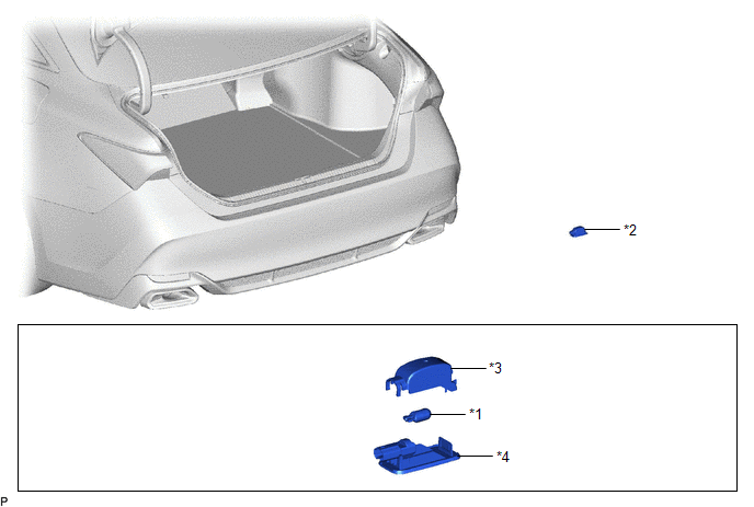
|
*1 | LUGGAGE COMPARTMENT LIGHT BULB |
*2 | NO. 1 LUGGAGE COMPARTMENT LIGHT ASSEMBLY |
|
*3 | SHADE |
*4 | NO. 1 LUGGAGE COMPARTMENT LIGHT LENS |
Inspection
INSPECTION
PROCEDURE
1. INSPECT NO. 1 LUGGAGE COMPARTMENT LIGHT ASSEMBLY
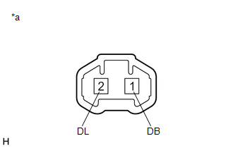
|
*a | Component without harness connected (No. 1 Luggage Compartment Light Assembly) |
(a) Apply auxiliary battery voltage to the No. 1 luggage compartment light assembly and check that the light illuminates.
OK:
|
Measurement Condition | Specified Condition |
|---|---|
|
Auxiliary battery positive (+) → 1 (DB) Auxiliary battery negative (-) → 2 (DL) |
Luggage compartment light illuminates |
If the result is not as specified, replace the bulb or No. 1 luggage compartment light assembly.
Installation
INSTALLATION
PROCEDURE
1. INSTALL LUGGAGE COMPARTMENT LIGHT BULB
(a) Install the luggage compartment light bulb to the No. 1 luggage compartment light lens as shown in the illustration.
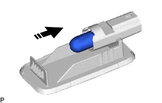
 |
Install in this Direction |
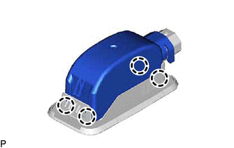
| (b) Engage the 4 claws to install the shade to the No. 1 luggage compartment light lens. |
|
2. INSTALL NO. 1 LUGGAGE COMPARTMENT LIGHT ASSEMBLY
(a) Connect the connector.
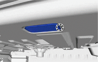
| (b) Engage the claw to install the No. 1 luggage compartment light assembly. |
|
Removal
REMOVAL
PROCEDURE
1. REMOVE NO. 1 LUGGAGE COMPARTMENT LIGHT ASSEMBLY
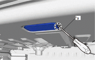
| (a) Using a screwdriver with its tip wrapped with protective tape, disengage the claw. |
|
(b) Disconnect the connector to remove the No. 1 luggage compartment light assembly.
2. REMOVE LUGGAGE COMPARTMENT LIGHT BULB
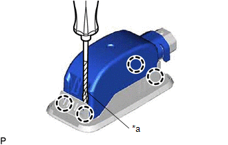
| (a) Using a screwdriver with its tip wrapped with protective tape, disengage the 4 claws to remove the shade from the No. 1 luggage compartment light lens. |
|
(b) Remove the luggage compartment light bulb from the No. 1 luggage compartment light lens as shown in the illustration.
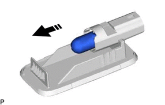
 |
Remove in this Direction |
Toyota Avalon (XX50) 2019-2022 Service & Repair Manual > 2gr-fks Emission Control: Fuel Tank Cap
InspectionINSPECTION PROCEDURE 1. INSPECT FUEL TANK CAP ASSEMBLY (a) Visually check that the fuel tank cap assembly and gasket are not deformed or damaged. If the result is not as specified, replace the fuel tank cap assembly. *a Gasket (b) Confirm that ID mark V is printed on the fuel tank cap ass ...