Components
COMPONENTS
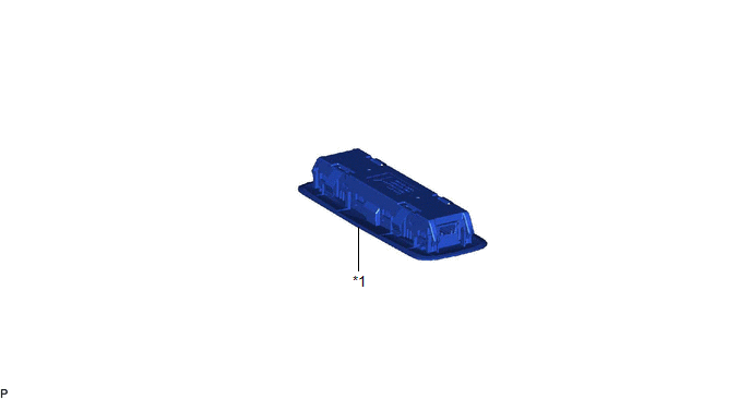
ILLUSTRATION
|
*1 | SPOT LIGHT ASSEMBLY |
- | - |
Inspection
INSPECTION
PROCEDURE
1. INSPECT SPOT LIGHT ASSEMBLY
|
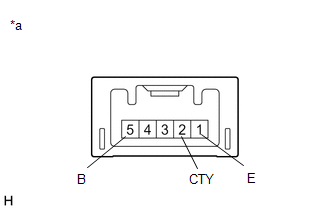
*a | Component without harness connected (Spot Light Assembly) |
(a) Apply auxiliary battery voltage to the spot light assembly and check that the lights illuminate.
OK:
|
Measurement Condition | Condition |
Specified Condition |
|---|---|---|
|
Auxiliary battery positive (+) → 5 (B) Auxiliary battery negative (-) → 1 (E) |
Spot light switch LH on |
Spot light LH illuminates |
|
Spot light switch RH on |
Spot light RH illuminates | |
|
Auxiliary battery positive (+) → 5 (B) Auxiliary battery negative (-) → 2 (CTY) |
Spot light switch LH off |
Spot light LH illuminates |
|
Spot light switch RH off |
Spot light RH illuminates |
If the result is not as specified, replace the spot light assembly.
Installation
INSTALLATION
PROCEDURE
1. INSTALL SPOT LIGHT ASSEMBLY
(a) Connect the connector.
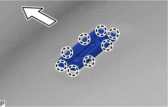
(b) Engage the 8 claws to install the spot light assembly.
 |
Front |
Removal
REMOVAL
PROCEDURE
1. REMOVE SPOT LIGHT ASSEMBLY
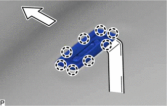
(a) Using a moulding remover, disengage the 8 claws.
 |
Front |
(b) Disconnect the connector to remove the spot light assembly.
Toyota Avalon (XX50) 2019-2022 Service & Repair Manual > Door / Hatch: Luggage Compartment Door Opener Outer Switch
ComponentsCOMPONENTS ILLUSTRATION *1 LUGGAGE ELECTRICAL KEY SWITCH - - InspectionINSPECTION PROCEDURE 1. INSPECT LUGGAGE ELECTRICAL KEY SWITCH (a) Check the switch. (1) Measure the resistance according to the value(s) in the table below. Standard Resistance: Tester Connection Condition Specified Co ...


