Odo/Trip Switch Malfunction
DESCRIPTION
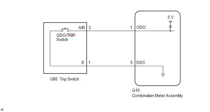
In this circuit, the combination meter assembly detects ODO/TRIP switch (trip switch) signals via a direct line.
WIRING DIAGRAM

CAUTION / NOTICE / HINT
NOTICE:
When
replacing the combination meter assembly, always replace it with a new
one. If a combination meter assembly which was installed to another
vehicle is used, the information stored in it will not match the
information from the vehicle and a DTC may be stored.
PROCEDURE
| 1. |
READ VALUE USING TECHSTREAM |
(a) Connect the Techstream to the DLC3.
(b) Turn the power switch on (IG).
(c) Turn the Techstream on.
(d) Enter the following menus: Body Electrical / Combination Meter / Data List.
(e) Read the Data List according to the display on the Techstream.
Body Electrical > Combination Meter > Data List
|
Tester Display | Measurement Item |
Range | Normal Condition |
Diagnostic Note |
|
ODO/TRIP Change Switch |
ODO/TRIP switch (Trip switch) |
OFF or ON | OFF: Switch released
ON: Switch pushed | - |
Body Electrical > Combination Meter > Data List
|
Tester Display |
| ODO/TRIP Change Switch |
OK:
ODO/TRIP switch (trip switch) condition displayed on the Techstream changes with the actual switch operation.
| OK |
 | REPLACE COMBINATION METER ASSEMBLY |
|
NG |
 | |
(a) Remove the trip switch.
Click here 
(b) Inspect the trip switch.
Click here 
| NG |
 | REPLACE TRIP SWITCH |
|
OK |
 | |
| 3. |
CHECK HARNESS AND CONNECTOR (TRIP SWITCH - COMBINATION METER ASSEMBLY) |
(a) Disconnect the G15 combination meter assembly connector.
(b) Measure the resistance according to the value(s) in the table below.
Standard Resistance:
|
Tester Connection | Condition |
Specified Condition |
|
G80-3 (A/B) - G15-1 (ODO) |
Always | Below 1 Ω |
|
G80-1 (E) - G15-5 (SW3) |
Always | Below 1 Ω |
|
G80-3 (A/B) or G15-1 (ODO) - Body ground |
Always | 10 kΩ or higher |
| OK |
 | REPLACE COMBINATION METER ASSEMBLY |
| NG |
 | REPAIR OR REPLACE HARNESS OR CONNECTOR |
On-vehicle Inspection
ON-VEHICLE INSPECTION
PROCEDURE
1. INSPECT COMBINATION METER ASSEMBLY
(a) Inspect speedometer operation
NOTICE:
- The combination meter assembly receives the vehicle speed signal from
the skid control ECU (brake booster with master cylinder assembly) via
CAN communication. Therefore, perform the following inspection referring
to values on the Data List of the skid control ECU (brake booster with
master cylinder assembly) because it is the source of the vehicle speed
signal.
- Data List values of the skid control ECU (brake booster with master
cylinder assembly) are used for this inspection. Therefore, make sure to
perform this inspection after confirming that DTCs are not output.
- If the tire size or tire inflation pressure is not within the specified
range, or the tires are excessively worn, the speedometer indication
error will increase. Therefore, make sure to perform this inspection
after checking that the tire size, tire inflation pressure and tire wear
are in the specified range.
(1) Warm up the engine.
(2) Connect the Techstream to the DLC3.
(3) Turn the power switch on (IG).
(4) Turn the Techstream on.
(5) Enter the following menus: Chassis / ABS/VSC/TRAC / Data List.
(6) Read the Data List according to the display on the Techstream.
Reference mph |
Techstream Indication (mph) |
Acceptable Range (mph) |
|
20 | 19.2 to 21.7 |
|
40 | 39.4 to 42.2 |
|
60 | 59.8 to 62.6 |
|
80 | 80.0 to 83.2 |
|
100 | 100.5 to 103.7 |
|
120 | 120.9 to 124.1 |
|
140 | 141.3 to 144.5 |
OK:
Speedometer reading is within the acceptable range at each vehicle speed.
Chassis > ABS/VSC/TRAC > Data List
|
Tester Display | Measurement Item |
Range | Normal Condition |
Diagnostic Note |
|
Vehicle Speed | Maximum wheel speed sensor |
Min.: 0 km/h (0 mph), Max.: 326.4 km/h (203 mph) |
Vehicle stopped: 0 km/h (0 mph) |
When driving at constant speed: No large fluctuations |
Chassis > ABS/VSC/TRAC > Data List
|
Tester Display |
| Vehicle Speed |
(b) Check LED illumination (LED check)
(1) Check the illumination function of the warning or indicator lights listed below when turning the power switch on (IG).
OK:
|
Warning or Indicator Light |
Specified Condition |
| Brake warning light / red (malfunction) |
Warning or indicator light comes on for about 3 seconds after turning the power switch on (IG). |
|
Slip indicator light |
|
VSC OFF indicator light |
| ABS warning light |
|
Tire pressure warning light |
|
Master warning light |
|
ICS OFF indicator light* |
|
Brake warning light / yellow (minor malfunction) |
|
Brake hold standby indicator light |
|
Brake hold operated indicator light |
|
PCS warning light |
| SRS warning light |
Warning light comes on for about 6 seconds after turning the power switch on (IG). |
|
EPS warning light | When
the power switch is turned on (IG), warning light (red) illuminates for
2 seconds and then the warning light (yellow) illuminates. |
|
MIL (Check engine warning light) | Warning light comes on when the power switch is turned on (IG). |
- *: w/ Intelligent Clearance Sonar System
Operating Light Control Rheostat does not Change Light Brightness
DESCRIPTION
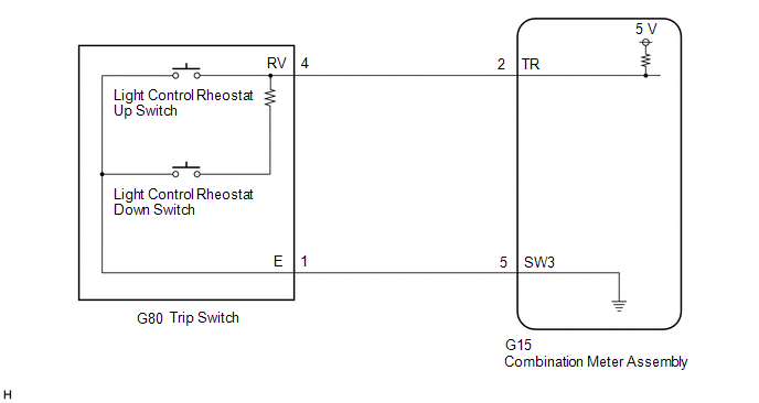
The combination
meter assembly receives signals through this circuit to adjust the
illumination of the combination meter assembly. The combination meter
assembly sets the illumination level based on the user operation of the
light control rheostat switch in the trip switch.
WIRING DIAGRAM

CAUTION / NOTICE / HINT
NOTICE:
When
replacing the combination meter assembly, always replace it with a new
one. If a combination meter assembly which was installed to another
vehicle is used, the information stored in it will not match the
information from the vehicle and a DTC may be stored.
HINT:
- The illumination level of the combination meter assembly can be adjusted
by pressing the light control rheostat switch (trip switch).
- The illumination of the combination meter assembly dims when the taillights are turned on.
- Setting the illumination to maximum brightness cancels the above dimming of the illumination.
PROCEDURE
|
1. | READ VALUE USING TECHSTREAM |
(a) Connect the Techstream to the DLC3.
(b) Turn the power switch on (IG).
(c) Turn the Techstream on.
(d) Enter the following menus: Body Electrical / Combination Meter / Data List.
(e) Read the Data List according to the display on the Techstream.
Body Electrical > Combination Meter > Data List
|
Tester Display | Measurement Item |
Range | Normal Condition |
Diagnostic Note |
|
Light Control Switch (UP) |
Light control rheostat up switch (Trip switch) |
OFF or ON | OFF: Switch released
ON: Switch pushed | - |
|
Light Control Switch (DOWN) |
Light control rheostat down switch (Trip switch) |
OFF or ON | OFF: Switch released
ON: Switch pushed | - |
Body Electrical > Combination Meter > Data List
|
Tester Display |
| Light Control Switch (UP) |
|
Light Control Switch (DOWN) |
OK:
Light
control rheostat up or down switch (trip switch) condition displayed on
the Techstream changes with the actual switch operation.
| OK |
 | REPLACE COMBINATION METER ASSEMBLY |
|
NG |
 | |
(a) Remove the trip switch.
Click here 
(b) Inspect the trip switch.
Click here 
| NG |
 | REPLACE TRIP SWITCH |
|
OK |
 | |
| 3. |
CHECK HARNESS AND CONNECTOR (TRIP SWITCH - COMBINATION METER ASSEMBLY) |
(a) Disconnect the G15 combination meter assembly connector.
(b) Measure the resistance according to the value(s) in the table below.
Standard Resistance:
|
Tester Connection | Condition |
Specified Condition |
|
G80-4 (RV) - G15-2 (TR) |
Always | Below 1 Ω |
|
G80-1 (E) - G15-5 (SW3) |
Always | Below 1 Ω |
|
G80-4 (RV) or G15-2 (TR) - Body ground |
Always | 10 kΩ or higher |
| OK |
 | REPLACE COMBINATION METER ASSEMBLY |
| NG |
 | REPAIR OR REPLACE HARNESS OR CONNECTOR |


