PARTS LOCATION ILLUSTRATION *1 FUEL SENDER GAUGE ASSEMBLY *2 LEVEL WARNING SWITCH ASSEMBLY *3 PARKING BRAKE ECU (BRAKE ACTUATOR ASSEMBLY) *4 POWER STEERING ECU (RACK AND PINION POWER STEERING GEAR ASSEMBLY) *5 INVERTER WITH CONVERTER ASSEMBLY *6 ECM *7 SKID CONTROL ECU (BRAKE BOOSTER WITH MASTER CYLINDER ASSEMBLY) *8 FORWARD RECOGNITION CAMERA *9 SWING GRILLE ACTUATOR ASSEMBLY *10 FUEL SUCTION TUBE WITH PUMP AND GAUGE ASSEMBLY ILLUSTRATION *A w/ Cornering Light - - *1 HEADLIGHT ASSEMBLY LH *2 HEADLIGHT ASSEMBLY RH *3 OUTER REAR VIEW MIRROR SUB-ASSEMBLY LH *4 OUTER REAR VIEW MIRROR SUB-ASSEMBLY RH *5 REAR COMBINATION LIGHT ASSEMBLY LH *6 REAR COMBINATION LIGHT ASSEMBLY RH *7 REAR LIGHT ASSEMBLY LH *8 REAR LIGHT ASSEMBLY RH *9 SIDE TURN SIGNAL LIGHT ASSEMBLY LH *10 SIDE TURN SIGNAL LIGHT ASSEMBLY RH *11 HEADLIGHT ECU SUB-ASSEMBLY LH *12 HEADLIGHT ECU SUB-ASSEMBLY RH *13 REAR COMBINATION LIGHT SOCKET AND WIRE LH *14 REAR COMBINATION LIGHT SOCKET AND WIRE RH *15 BLIND SPOT MONITOR SENSOR RH *16 ELECTRICAL KEY AND TIRE PRESSURE WARNING ECU AND RECEIVER *17 REAR LIGHT CORD LH *18 REAR LIGHT CORD RH ILLUSTRATION *A w/ Navigation System *B for 14 Speakers *C w/ Intelligent Clearance Sonar System *D w/ Headup Display System *1 AIRBAG ECU ASSEMBLY *2 HAZARD WARNING SWITCH ASSEMBLY *3 SPIRAL CABLE SUB-ASSEMBLY *4 STEERING PAD SWITCH ASSEMBLY *5 TRIP SWITCH *6 AIR CONDITIONING AMPLIFIER ASSEMBLY *7 DCM (TELEMATICS TRANSCEIVER) *8 COMBINATION METER ASSEMBLY *9 INSTRUMENT PANEL JUNCTION BLOCK ASSEMBLY - ECU-DCC NO. 2 FUSE - METER-IG2 FUSE - HAZ FUSE *10 MAIN BODY ECU (MULTIPLEX NETWORK BODY ECU) *11 STEREO COMPONENT AMPLIFIERASSEMBLY *12 CERTIFICATION ECU (SMART KEY ECU ASSEMBLY) *13 DLC3 *14 RADIO AND DISPLAY RECEIVER ASSEMBLY *15 CLEARANCE WARNING ECU ASSEMBLY *16 STEERING SENSOR *17 REAR SEAT BELT WARNING LIGHT *18 ODO/TRIP SWITCH *19 LIGHT CONTROL RHEOSTAT SWITCH *20 NAVIGATION ECU *21 DRIVING SUPPORT ECU ASSEMBLY *22 METER MIRROR SUB-ASSEMBLY *23 HYBRID VEHICLE CONTROL ECU *24 VEHICLE APPROACHING SPEAKER CONTROLLER ILLUSTRATION *1 REAR SEAT INNER BELT ASSEMBLY LH *2 REAR SEAT INNER WITH CENTER BELT ASSEMBLY RH ILLUSTRATION *1 ENGINE OIL LEVEL SENSOR - - PRECAUTION NOTICE: When
disconnecting the cable from the negative (-) auxiliary battery
terminal, initialize the following systems after the cable is
reconnected. System Name See Procedure Lane Departure Alert System (w/ Steering Control) Intelligent Clearance Sonar System Parking Assist Monitor System Panoramic View Monitor System Pre-collision System Lighting System (for HV Model with Cornering Light) PRECAUTION FOR DISCONNECTING CABLE FROM NEGATIVE AUXILIARY BATTERY TERMINAL PRECAUTION FOR REPLACING COMBINATION METER ASSEMBLY When
replacing the combination meter assembly, always replace it with a new
one. If a combination meter assembly which was installed to another
vehicle is used, the information stored in it will not match the
information from the vehicle and a DTC may be stored. FUEL RECEIVER GAUGE OPERATION (a) OPERATION The
combination meter assembly uses the fuel sender gauge assembly to
detect the amount of fuel remaining in the fuel tank assembly. The Hall
IC built into the fuel sender gauge assembly changes the output voltage
according to the amount of fuel remaining. The combination meter
assembly receives fuel injection volume signals from the ECM and detects
the voltage output from the fuel sender gauge assembly and operates the
fuel receiver gauge. (b) FUEL RECEIVER GAUGE READING (1) During normal driving: As
the fuel level in the fuel tank assembly changes when driving on a hill
or applying the brakes, the fuel receiver gauge reading is updated
according to the fuel injection volume during normal driving. However,
as the fuel injection volume measurement has a margin of error, the
value is indicated after correction by input values from the fuel sender
gauge assembly. (2) During refueling: The
fuel level in the fuel tank assembly rises rapidly when fuel is added.
If the averaging process that is used during normal driving is used in
this case, the fuel receiver gauge reading cannot be updated promptly.
Therefore, when it is judged that fuel is being added to the vehicle
based on the changes in the fuel level, output values from the fuel
sender gauge assembly is immediately reflected in the fuel receiver
gauge reading. This control is called refueling judgment. (c) REFUELING JUDGMENT CONDITIONS NOTICE: Add
fuel with the power switch off to ensure safety and to enable refueling
judgment so that an appropriate fuel receiver gauge reading will be
obtained. (1) Normal judgment condition (When normal refueling method is used) With
the power switch off, the fuel sender gauge assembly detects a change
of 7.0 liters (7.4 US qts, 6.2 Imp. qts) or more in the fuel level. (2) Other judgment conditions (When other refueling method is used) Any of the following conditions is met: (d) PRECAUTION FOR REFUELING (1)
The fuel sender gauge assembly cannot detect changes in the fuel level
within certain ranges (around points E and F). Therefore, even if 7.0
liters (7.4 US qts, 6.2 Imp. qts) or more of fuel is added, refueling
judgment may not be performed and the fuel receiver gauge reading may
not change when fuel level is within such ranges. (2)
The fuel sender gauge reading takes approximately 25 seconds to rise
from point E to F. If the vehicle is driven while the fuel sender gauge
reading is rising, the fuel sender gauge reading will stop rising. After
the fuel sender gauge reading stops rising, normal fuel sender gauge
reading operation begins. The fuel sender gauge reading takes
approximately 1 minute per 1 liter (1.1 US qts, 0.9 Imp. qts) to rise
while the vehicle is being driven, and takes approximately 8 minutes per
1 liter (1.1 US qts, 0.9 Imp. qts) to rise while the vehicle is
stopped. (e) FORCED RESET OF FUEL RECEIVER GAUGE When
driving at a vehicle speed of 1.8 km/h (1 mph) or more, if the output
value from the fuel sender gauge assembly is different from the fuel
receiver gauge reading by 15.0 liters (15.9 US qts, 13.2 Imp. qts) or
more for approximately 5 minutes, the output value from the fuel sender
gauge assembly is immediately reflected in the fuel receiver gauge
reading to compensate for a situation when refueling judgment cannot be
made. SERVICE MODE (w/ Toyota Entune Remote Connect) NOTICE: (a) Service mode HINT: To cancel service mode, turn the power switch off and on (IG) to display the service mode screen and cancel service mode. (1) Service mode (Using the Techstream) (2) Service mode (When not using the Techstream) w/o Navigation System: Click here w/ Navigation System: Click here PROBLEM SYMPTOMS TABLE NOTICE: When
replacing the combination meter assembly, always replace it with a new
one. If a combination meter assembly which was installed to another
vehicle is used, the information stored in it will not match the
information from the vehicle and a DTC may be stored. HINT: Click here Symptom Suspected Area Link Speedometer malfunction Speedometer circuit
Hybrid system indicator malfunction Hybrid system indicator circuit Fuel receiver gauge display malfunction Fuel receiver gauge display circuit Engine coolant temperature receiver gauge malfunction Engine coolant temperature receiver gauge circuit Symptom Suspected Area Link Fuel level warning light malfunction (Fuel receiver gauge is normal) Combination meter assembly Malfunction other than above Combination meter assembly Symptom Suspected Area Link Multi-information display is not displayed Combination meter assembly Digital tachometer malfunction Tachometer circuit
Engine Oil Level Low Add or Replace display malfunction Engine oil level sensor circuit Proximity Notification System Malfunction Visit Your Dealer display malfunction Vehicle proximity notification system warning display circuit Close Fuel Lid display malfunction Fuel lid opener system operation display circuit Ready to Refuel display malfunction Fuel lid opener system operation display circuit Please Wait Fuel Door Opening display malfunction Fuel lid opener system operation display circuit Malfunction other than above Combination meter assembly Symptom Suspected Area Link Buzzer malfunction Combination meter assembly Symptom Suspected Area Link Entire combination meter does not operate Power source circuit Operating ODO/TRIP switch (trip switch) does not change odometer/TRIP meter display ODO/TRIP switch circuit Operating steering pad switch does not change multi-information display Steering pad switch circuit Operating light control rheostat does not change light brightness Light control rheostat switch circuit Meter illumination malfunction Combination meter assembly Other systems that use the speed signal do not operate normally Speed signal circuit Parts Location
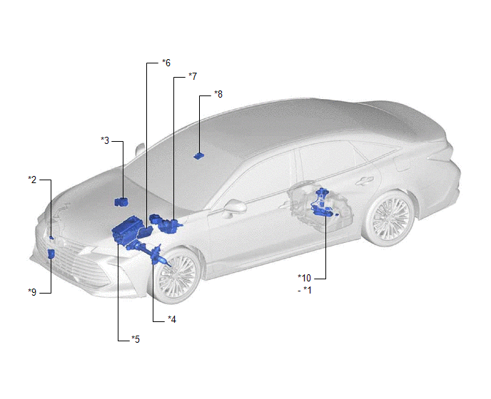
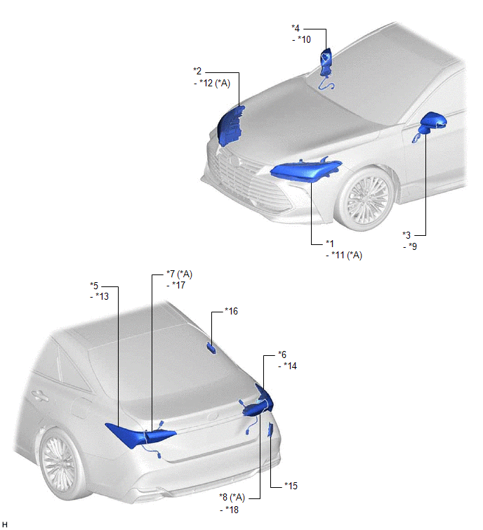
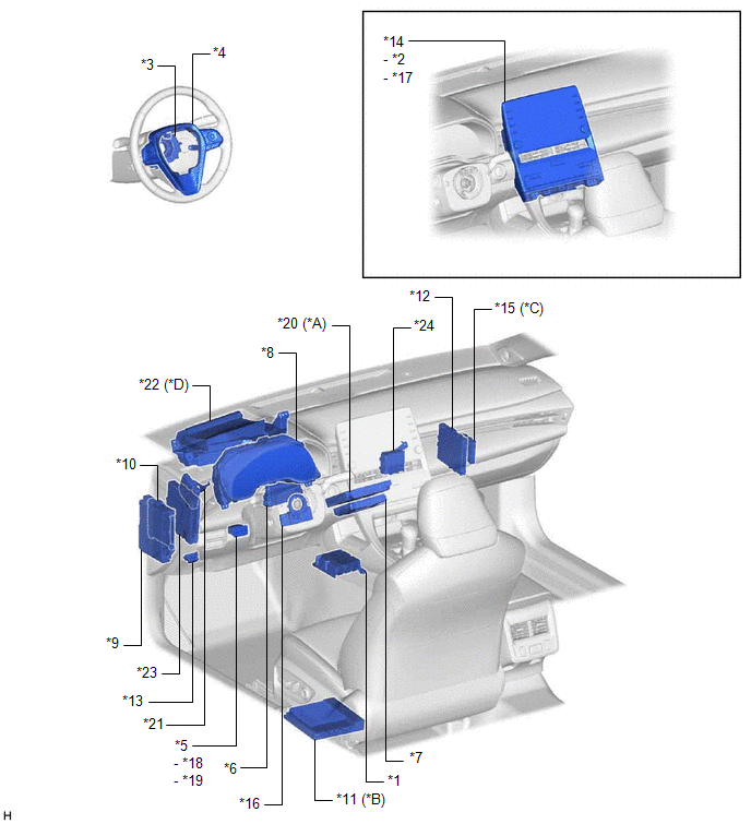
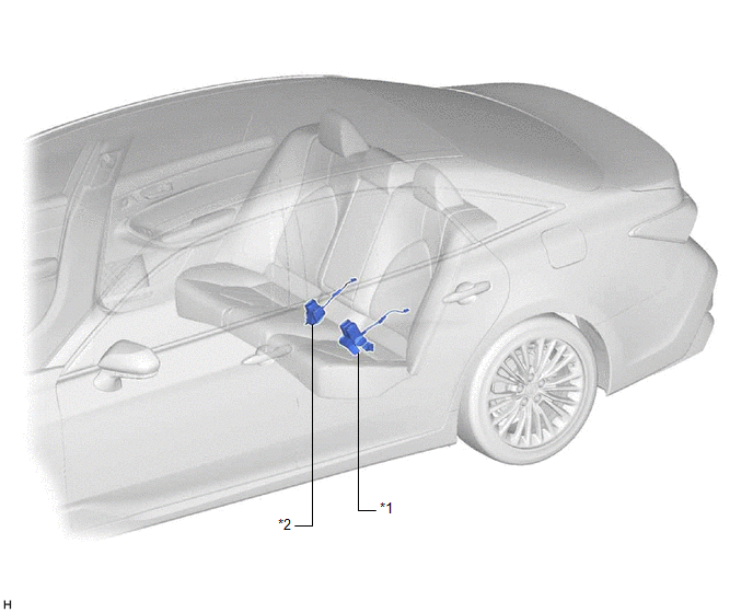
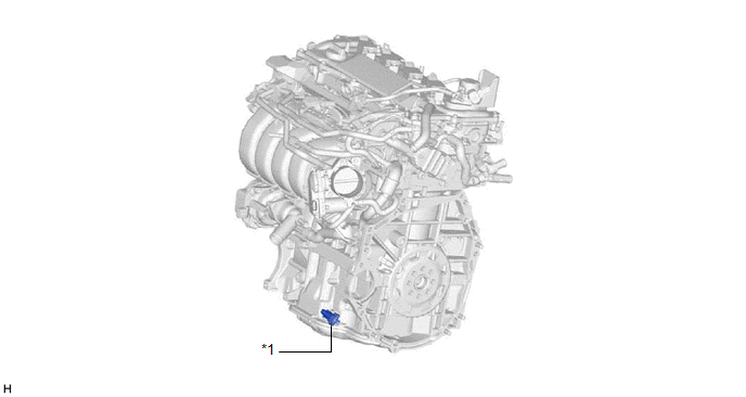
Precaution

Body Electrical > Telematics > Trouble Codes


Problem Symptoms Table
Meter or Gauge 
Warning or Indicator


Multi-information Display


Buzzer


Others


Toyota Avalon (XX50) 2019-2022 Service & Repair Manual > Electronically Controlled Brake System(for Hv Model): Motor Drive Permission Malfunction (C1451). Calibration. Check For Intermittent Problems
Motor Drive Permission Malfunction (C1451) DESCRIPTION If air bleeding has not been performed, the skid control ECU (brake booster with master cylinder assembly) stores DTC C1451 to prevent the entry of air due to pump motor operation. DTC C1451 is stored when Motor Invalid is selected, the system w ...