Front Radar Sensor Region Code Mismatch (C1A0A)
DESCRIPTION
The driving support ECU assembly uses the millimeter wave radar sensor assembly to detect objects in front of the vehicle.
Based
on signals from the millimeter wave radar sensor assembly, the driving
support ECU assembly calculates the possibility of a collision and
operates the pre-collision system if it determines that the possibility
is high.
When the millimeter wave radar sensor
assembly is replaced with a new one, it acquires the country
specification information from the driving support ECU assembly. Also,
when the driving support ECU assembly is replaced with a new one, it
receives country specification information from the main body ECU
(multiplex network body ECU). If country specification information in
the millimeter wave radar sensor assembly, driving support ECU and/or
main body ECU do not match, DTC C1A0A will be stored.
|
DTC No. | Detection Item |
DTC Detection Condition | Trouble Area |
|
C1A0A | Front Radar Sensor Region Code Mismatch |
When
the power switch is on (IG), the country specification information in
the driving support ECU assembly and millimeter wave radar sensor
assembly do not match for approximately 2 seconds. |
- Millimeter wave radar sensor assembly
- Driving support ECU assembly
|
CAUTION / NOTICE / HINT
NOTICE:
- When replacing the driving support ECU assembly, always replace it with a
new one. If a driving support ECU assembly which was installed to
another vehicle is used, the information stored in the driving support
ECU assembly will not match the information from the vehicle. As a
result, a DTC may be stored.
- When replacing the millimeter wave radar sensor assembly, always replace
it with a new one. If a millimeter wave radar sensor assembly which was
installed to another vehicle is used, the information stored in the
millimeter wave radar sensor assembly will not match the information
from the vehicle. As a result, a DTC may be stored.
- When the millimeter wave radar sensor assembly is replaced with a new
one, adjustment of the radar sensor beam axis must be performed.
Click here 
- The pre-collision system uses the CAN communication system. First,
confirm that there are no malfunctions in the CAN communication system.
Refer to How to Proceed with Troubleshooting.
Click here 
PROCEDURE
(a) Clear the DTCs.
Body Electrical > Pre-Collision 2 > Clear DTCs
(b) Make sure that the DTC detection conditions are met.
HINT:
If the detection conditions are not met, the system cannot detect the malfunction.
(c) Check for DTCs.
Body Electrical > Pre-Collision 2 > Trouble Codes
|
Result | Proceed to |
|
DTC C1A0A is not output |
A |
| DTC C1A0A is output |
B |
| A |
 | USE SIMULATION METHOD TO CHECK |
|
B |
 | |
| 2. |
REPLACE DRIVING SUPPORT ECU ASSEMBLY |
(a) Replace the driving support ECU assembly.
Click here 
|
NEXT |
 | |
(a) Clear the DTCs.
Body Electrical > Pre-Collision 2 > Clear DTCs
(b) Make sure that the DTC detection conditions are met.
HINT:
If the detection conditions are not met, the system cannot detect the malfunction.
(c) Check for DTCs.
Body Electrical > Pre-Collision 2 > Trouble Codes
|
Result | Proceed to |
|
DTC C1A0A is not output |
A |
| DTC C1A0A is output |
B |
| A |
 | END (DRIVING SUPPORT ECU ASSEMBLY WAS DEFECTIVE) |
|
B |
 | |
| 4. |
REPLACE MILLIMETER WAVE RADAR SENSOR ASSEMBLY |
(a) Replace the millimeter wave radar sensor assembly.
Click here

(b) Adjust the millimeter wave radar sensor assembly.
Click here 
| NEXT |
 | END (MILLIMETER WAVE RADAR SENSOR ASSEMBLY WAS DEFECTIVE) |
Driving Support ECU (C1A01)
DESCRIPTION
The driving support ECU assembly uses the millimeter wave radar sensor assembly to detect objects in front of the vehicle.
Based
on signals from the millimeter wave radar sensor assembly, the driving
support ECU assembly calculates the possibility of a collision and
operates the pre-collision system if it determines that the possibility
is high.
|
DTC No. | Detection Item |
DTC Detection Condition | Trouble Area |
|
C1A01 | Driving Support ECU |
When the power switch is on (IG), the driving support ECU assembly detects an internal malfunction for approximately 1 second. |
Driving support ECU assembly |
CAUTION / NOTICE / HINT
NOTICE:
When
replacing the driving support ECU assembly, always replace it with a
new one. If a driving support ECU assembly which was installed to
another vehicle is used, the information stored in the driving support
ECU assembly will not match the information from the vehicle. As a
result, a DTC may be stored.
PROCEDURE
| 1. |
REPLACE DRIVING SUPPORT ECU ASSEMBLY |
(a) Replace the driving support ECU assembly.
Click here 
| NEXT |
 | END |
Vehicle Information Not Obtained (C1A02)
DESCRIPTION
When a new
driving support ECU assembly is installed, it receives vehicle
specification information (destination, steering wheel position, etc.)
from the main body ECU (multiplex network body ECU) and stores the
information.
DTC C1A02 is stored when the
driving support ECU assembly receives the vehicle specification
information from the main body ECU (multiplex network body ECU) but
cannot store it.
|
DTC No. | Detection Item |
DTC Detection Condition | Trouble Area |
|
C1A02 | Vehicle Information Not Obtained |
The
vehicle specification information of the main body ECU (multiplex
network body ECU) and driving support ECU assembly do not match for 1
second or more while the vehicle is being driven at a speed of 50 km/h
(32 mph) or more. | Driving support ECU assembly |
CAUTION / NOTICE / HINT
NOTICE:
- When replacing the driving support ECU assembly, always replace it with a
new one. If a driving support ECU assembly which was installed to
another vehicle is used, the information stored in the driving support
ECU assembly will not match the information from the vehicle. As a
result, a DTC may be stored.
- The pre-collision system uses the CAN communication system. First,
confirm that there are no malfunctions in the CAN communication system.
Refer to How to Proceed with Troubleshooting.
Click here 
PROCEDURE
|
1. | REPLACE DRIVING SUPPORT ECU ASSEMBLY |
(a) Replace the driving support ECU assembly.
Click here

| NEXT |  |
END |
Stop Light Relay Circuit (C1A4B)
DESCRIPTION
The skid
control ECU (brake booster with master cylinder assembly) sends a stop
light operation request signal to the stop light relay (stop light
switch assembly). If the skid control ECU (brake booster with master
cylinder assembly) detects a malfunction in the stop light relay (stop
light switch assembly) circuit, the driving support ECU assembly stores
DTC C1A4B.
|
DTC No. | Detection Item |
DTC Detection Condition | Trouble Area |
|
C1A4B | Stop Light Relay Circuit |
Both of the following conditions are met:
- All of the following conditions are met:
- 3 seconds have elapsed since the power switch was turned to on (IG).
- The battery voltage is 10 V or more for 3 seconds or more.
- All of the following conditions are met for 1 second or more:
- Communication between the driving support ECU assembly and skid control
ECU (brake booster with master cylinder assembly) is normal.
- The driving support ECU assembly receives a stop light relay circuit
malfunction signal from the skid control ECU (brake booster with master
cylinder assembly)
| Electronically controlled brake system |
CAUTION / NOTICE / HINT
NOTICE:
The
pre-collision system uses the CAN communication system. First, confirm
that there are no malfunctions in the CAN communication system. Refer to
How to Proceed with Troubleshooting.
Click here

PROCEDURE
| 1. |
GO TO ELECTRONICALLY CONTROLLED BRAKE SYSTEM |
HINT:
If DTC C1A4B is output by the pre-collision system, perform troubleshooting for the electronically controlled brake system.
Click here 
| NEXT |
 | END |
Front Radar Sensor (C1A10)
DESCRIPTION
The driving support ECU assembly uses the millimeter wave radar sensor assembly to detect objects in front of the vehicle.
Based
on this signals from the millimeter wave radar sensor assembly, the
driving support ECU assembly sends pre-collision system control
operation signals.
If the driving support ECU
assembly receives an internal malfunction signal from the millimeter
wave radar sensor assembly, it stores DTC C1A10.
|
DTC No. | Detection Item |
DTC Detection Condition | Trouble Area |
|
C1A10 | Front Radar Sensor |
When
the power switch is on (IG), the driving support ECU assembly receives
an internal malfunction signal from the millimeter wave radar sensor
assembly for approximately 0.2 seconds. |
Millimeter wave radar sensor assembly |
CAUTION / NOTICE / HINT
NOTICE:
- When replacing the millimeter wave radar sensor assembly, always replace
it with a new one. If a millimeter wave radar sensor assembly which was
installed to another vehicle is used, the information stored in the
millimeter wave radar sensor assembly will not match the information
from the vehicle. As a result, a DTC may be stored.
- When the millimeter wave radar sensor assembly is replaced with a new
one, adjustment of the radar sensor beam axis must be performed.
Click here 
- The pre-collision system uses the CAN communication system. First,
confirm that there are no malfunctions in the CAN communication system.
Refer to How to Proceed with Troubleshooting.
Click here 
PROCEDURE
|
1. | REPLACE MILLIMETER WAVE RADAR SENSOR ASSEMBLY |
(a) Replace the millimeter wave radar sensor assembly.
Click here

(b) Adjust the millimeter wave radar sensor assembly.
Click here 
| NEXT |
 | END |
Front Radar Sensor Incorrect Axial Gap (C1A11,C1A14)
DESCRIPTION
The driving support ECU assembly uses the millimeter wave radar sensor assembly to detect obstacles in front of the vehicle.
Based
on signals from the millimeter wave radar sensor assembly, the driving
support ECU assembly sends pre-collision system control operation
signals.
When the vehicle is determined to be
driving in a straight line or on a gradual curve based on signals from
the yaw rate sensor, etc., the millimeter wave radar sensor assembly
performs self diagnosis to check if the sensor beam axis has deviated.
If the millimeter wave radar sensor assembly beam axis has deviated, the
driving support ECU assembly detects this and stores DTC C1A11.
After
installing a new millimeter wave radar sensor assembly, if sensor beam
axis adjustment has not been performed, DTC C1A14 will be stored.
|
DTC No. | Detection Item |
DTC Detection Condition | Trouble Area |
|
C1A11 | Front Radar Sensor Incorrect Axial Gap |
When
the power switch is on (IG), misalignment of the millimeter wave radar
sensor assembly is detected for approximately 0.2 seconds. |
Millimeter wave radar sensor assembly |
|
C1A14 | Front Radar Sensor Beam Axis Not Adjusted |
When
the vehicle is being driven at a speed of 10 km/h (7 mph) or more,
incompletion of the millimeter wave radar sensor assembly beam axis
alignment is detected for approximately 0.2 seconds. |
Millimeter wave radar sensor assembly |
CAUTION / NOTICE / HINT
NOTICE:
- When replacing the millimeter wave radar sensor assembly, always replace
it with a new one. If a millimeter wave radar sensor assembly which was
installed to another vehicle is used, the information stored in the
millimeter wave radar sensor assembly will not match the information
from the vehicle. As a result, a DTC may be stored.
- When the millimeter wave radar sensor assembly is replaced with a new
one, adjustment of the radar sensor beam axis must be performed.
Click here 
PROCEDURE
|
1. | ADJUST MILLIMETER WAVE RADAR SENSOR ASSEMBLY |
(a) Perform millimeter wave radar sensor assembly adjustment.
Click here

|
NEXT |
 | |
(a) Clear the DTCs.
Body Electrical > Pre-Collision 2 > Clear DTCs
(b) Make sure that the DTC detection conditions are met.
HINT:
If the detection conditions are not met, the system cannot detect the malfunction.
(c) Check for DTCs.
Body Electrical > Pre-Collision 2 > Trouble Codes
|
Result | Proceed to |
|
DTC C1A11 and C1A14 are not output |
A |
| DTC C1A11 or C1A14 is output |
B |
| A |
 | END |
| B |
 | REPLACE MILLIMETER WAVE RADAR SENSOR ASSEMBLY |
Yaw Rate Sensor (C1A46)
DESCRIPTION
The driving
support ECU assembly receives yaw rate sensor signals from the airbag
ECU assembly and skid control ECU (brake booster with master cylinder
assembly) via CAN communication. If the driving support ECU assembly
receives a yaw rate sensor malfunction signal from the airbag ECU
assembly or skid control ECU (brake booster with master cylinder
assembly), DTC C1A46 will be stored.
|
DTC No. | Detection Item |
DTC Detection Condition | Trouble Area |
|
C1A46 | Yaw Rate Sensor |
- While the vehicle is being driven at a speed of 5 km/h (4 mph) or more,
the driving support ECU assembly receives a yaw rate sensor malfunction
signal from airbag ECU assembly for approximately 10 seconds.
- While the vehicle is being driven at a speed of 5 km/h (4 mph) or more,
the driving support ECU assembly receives a yaw rate sensor zero point
malfunction signal from skid control ECU (brake booster with master
cylinder assembly) for approximately 10 seconds.
| Electronically controlled brake system |
DTC Detection Conditions: | |
Vehicle Condition |
|
Pattern 1 | Pattern 2 |
|
Malfunction Status | Vehicle is being driven at a speed of 5 km/h (4 mph) or more |
â—‹ | â—‹ |
|
Driving support ECU assembly receives a yaw rate sensor malfunction signal from airbag ECU assembly |
â—‹ | - |
|
Driving
support ECU assembly receives a yaw rate sensor zero point malfunction
signal from skid control ECU (brake booster with master cylinder
assembly) | - |
â—‹ |
|
Detection Time | Approximately 10 seconds or more |
Approximately 10 seconds or more |
|
Number of Trips | 1 trip |
1 trip |
HINT:
DTC will be stored when the conditions of any pattern in the table above are met.
CAUTION / NOTICE / HINT
NOTICE:
The
pre-collision system uses the CAN communication system. First, confirm
that there are no malfunctions in the CAN communication system. Refer to
How to Proceed with Troubleshooting.
Click here

PROCEDURE
| 1. |
GO TO ELECTRONICALLY CONTROLLED BRAKE SYSTEM |
HINT:
If DTC C1A46 is output by the pre-collision system, perform troubleshooting for the electronically controlled brake system.
Click here 
| NEXT |
 | END |
Steering Angle Sensor (C1A47)
DESCRIPTION
The driving
support ECU assembly receives steering angle information from the
steering sensor. If the driving support ECU assembly detects a steering
sensor malfunction, DTC C1A47 will be stored.
|
DTC No. | Detection Item |
DTC Detection Condition | Trouble Area |
|
C1A47 | Steering Angle Sensor |
While
the vehicle is being driven at a speed of 50 km/h (32 mph) or more, the
driving support ECU assembly receives a steering sensor malfunction
signal continuously for 1 second or more. |
Electronically controlled brake system |
CAUTION / NOTICE / HINT
NOTICE:
The
pre-collision system uses the CAN communication system. First, confirm
that there are no malfunctions in the CAN communication system. Refer to
How to Proceed with Troubleshooting.
Click here

PROCEDURE
| 1. |
GO TO ELECTRONICALLY CONTROLLED BRAKE SYSTEM |
HINT:
If DTC C1A47 is output by the pre-collision system, perform troubleshooting for the electronically controlled brake system.
Click here 
| NEXT |
 | END |
Brake System Malfunction (C1A50)
DESCRIPTION
When the
pre-collision system is operating, the driving support ECU assembly
sends brake control signals to the skid control ECU (brake booster with
master cylinder assembly).
If the driving
support ECU assembly receives an electronically controlled brake system
malfunction signal from the skid control ECU (brake booster with master
cylinder assembly) via CAN communication, DTC C1A50 will be stored.
|
DTC No. | Detection Item |
DTC Detection Condition | Trouble Area |
|
C1A50 | Brake System Malfunction |
While
the power switch is on (IG), the driving support ECU assembly receives
an electronically controlled brake system malfunction signal from the
skid control ECU (brake booster with master cylinder assembly) for 0.3
seconds or more. | Electronically controlled brake system |
CAUTION / NOTICE / HINT
NOTICE:
The
pre-collision system uses the CAN communication system. First, confirm
that there are no malfunctions in the CAN communication system. Refer to
How to Proceed with Troubleshooting.
Click here

PROCEDURE
| 1. |
GO TO ELECTRONICALLY CONTROLLED BRAKE SYSTEM |
HINT:
If DTC C1A50 is output by the pre-collision system, perform troubleshooting for the electronically controlled brake system.
Click here 
| NEXT |
 | END |
Other System Malfunction (C1A63)
DESCRIPTION
If the hybrid
vehicle control ECU detects a malfunction in the hybrid control system,
it outputs a malfunction signal to the driving support ECU assembly via
CAN communication and this DTC is stored.
|
DTC No. | Detection Item |
DTC Detection Condition | Trouble Area |
|
C1A63 | Other System Malfunction |
With
the power switch on (IG), the driving support ECU assembly receives a
hybrid system malfunction signal from the hybrid vehicle control ECU for
approximately 2 seconds or more. |
Hybrid control system |
PROCEDURE
| 1. |
GO TO HYBRID CONTROL SYSTEM |
HINT:
If DTC C1A63 is output by the pre-collision system, perform troubleshooting for the hybrid control system.
Click here 
| NEXT |
 | END |
Brake Control Signal Mismatch (C1A64)
DESCRIPTION
The skid
control ECU (brake booster with master cylinder assembly) sends signals
to the driving support ECU assembly according to the brake control
status. If the driving support ECU assembly receives an electronically
controlled brake system malfunction signal from the skid control ECU
(brake booster with master cylinder assembly), it will store DTC C1A64.
|
DTC No. | Detection Item |
DTC Detection Condition | Trouble Area |
|
C1A64 | Brake Control Signal Mismatch |
While
the power switch is on (IG), the driving support ECU assembly receives
an electronically controlled brake system malfunction signal from the
skid control ECU (brake booster with master cylinder assembly)
continuously for 0.5 seconds or more. |
Electronically controlled brake system |
CAUTION / NOTICE / HINT
NOTICE:
The
pre-collision system uses the CAN communication system. First, confirm
that there are no malfunctions in the CAN communication system. Refer to
How to Proceed with Troubleshooting.
Click here

PROCEDURE
| 1. |
GO TO ELECTRONICALLY CONTROLLED BRAKE SYSTEM |
HINT:
If DTC C1A64 is output by the pre-collision system, perform troubleshooting for the electronically controlled brake system.
Click here 
| NEXT |
 | END |
Front Camera Module Circuit (C1AA0)
DESCRIPTION
The driving
support ECU assembly receives information about the area in front of the
vehicle from the forward recognition camera.
If the driving support ECU assembly detects a malfunction in the forward recognition camera, it will store DTC C1AA0.
|
DTC No. | Detection Item |
DTC Detection Condition | Trouble Area |
|
C1AA0 | Front Camera Module Circuit |
While
the power switch is on (IG), the forward recognition camera detects an
internal malfunction for approximately 0.3 seconds or more. |
Forward recognition camera |
CAUTION / NOTICE / HINT
NOTICE:
- When replacing the forward recognition camera, always replace it with a
new one. If a forward recognition camera which was installed to another
vehicle is used, the information stored in the forward recognition
camera will not match the information from the vehicle. As a result, a
DTC may be stored.
- If the forward recognition camera has been replaced with a new one, be sure to perform forward recognition camera adjustment.
Click here 
- The pre-collision system uses the CAN communication system. First,
confirm that there are no malfunctions in the CAN communication system.
Refer to How to Proceed with Troubleshooting.
Click here 
PROCEDURE
|
1. | REPLACE FORWARD RECOGNITION CAMERA |
(a) Replace the forward recognition camera.
Click here

(b) Perform forward recognition camera adjustment.
Click here 
| NEXT |
 | END |
Front Camera Module Beam Axis Not Adjusted (C1AA9)
DESCRIPTION
If forward
recognition camera adjustment has not been performed or did not complete
normally after the forward recognition camera was replaced with a new
one, DTC C1AA9 will be stored.
|
DTC No. | Detection Item |
DTC Detection Condition | Trouble Area |
|
C1AA9 | Front Camera Module Beam Axis Not Adjusted |
When
the pre-collision system is on, the driving support ECU assembly
detects that forward recognition camera adjustment has not been
completed for 0.3 seconds or more. |
Front camera system |
PROCEDURE
| 1. |
GO TO FRONT CAMERA SYSTEM |
HINT:
If DTC C1AA9 is output by the pre-collision system, perform troubleshooting for the front camera system.
Click here 
| NEXT |
 | END |
Heater Circuit (C1AAE)
DESCRIPTION
If the forward
recognition camera detects a malfunction in the forward recognition with
heater hood sub-assembly circuit, it will output a malfunction signal
to the driving support ECU assembly via CAN communication and this DTC
will be stored.
|
DTC No. | Detection Item |
DTC Detection Condition | Trouble Area |
|
C1AAE | Heater Circuit |
When
the power switch is on (IG), the driving support ECU assembly receives a
forward recognition with heater hood sub-assembly malfunction signal
from the forward recognition camera continuously for 1 second or more. |
Front camera system |
PROCEDURE
| 1. |
GO TO FRONT CAMERA SYSTEM |
HINT:
If DTC C1AAE is output by the pre-collision system, perform troubleshooting for the front camera system.
Click here 
| NEXT |
 | END |
Customize Parameters
CUSTOMIZE PARAMETERS
NOTICE:
- When the customer requests a change in a function, first make sure that the function can be customized.
- Make a note of the current settings before customizing.
HINT:
The following PCS functions and the pre-collision system sensitivity setting can be changed from their default setting.
CUSTOMIZE PRE-COLLISION SYSTEM
(a) Customizing with the Techstream
(1) Turn the power switch off.
(2) Connect the Techstream to the DLC3.
(3) Turn the power switch on (IG).
(4) Turn the Techstream on.
(5) Enter the following menus: Customize Setting / Others.
(6) Select the setting by referring to the table below.
Others
|
Tester Display | Description |
Default | Setting |
ECU |
| PCS Operation State Retention Setting |
Refer to the table below |
OFF | 0:OFF,1:ON |
Driving support ECU assembly |
|
PCS Alarm Activation Distance Retention Setting 1 |
Refer to the table below |
OFF | 0:OFF,1:ON |
Driving support ECU assembly |
|
PCS Alarm Activation Distance Retention Setting 2 |
Refer to the table below |
ON | 0:OFF,1:ON |
Driving support ECU assembly |
|
PCS Alarm Activation Distance Retention Setting 3 |
Refer to the table below |
OFF | 0:OFF,1:ON |
Driving support ECU assembly |
|
Customize Setting | Description |
Setting |
| PCS Operation State Retention Setting |
Function to maintain the pre-collision system on/off setting when the power switch is turned off and then on (IG). |
OFF: Not maintained (Pre-collision system always turns on) ON: Maintained |
|
PCS Alarm Activation Distance Retention Setting 1 |
Function
to maintain the sensitivity setting of the pre-collision system when
the pre-collision system is turned off and then on. |
OFF: Not maintained (Setting changes to "Mid") ON: Maintained |
|
PCS Alarm Activation Distance Retention Setting 2 |
Function
to maintain the sensitivity setting of the pre-collision system when
the power switch is turned off while the pre-collision system is on. |
OFF: Not maintained (Setting changes to "Mid") ON: Maintained |
|
PCS Alarm Activation Distance Retention Setting 3 |
Function
to maintain the sensitivity setting of the pre-collision system when
the power switch is turned off while the pre-collision system is off. |
OFF: Not maintained (Setting changes to "Mid") ON: Maintained |
Data List / Active Test
DATA LIST / ACTIVE TEST
DATA LIST
NOTICE:
In
the table below, the values listed under "Normal Condition" are
reference values. Do not depend solely on these reference values when
deciding whether a part is faulty or not.
HINT:
Using
the Techstream to read the Data List allows the values or states of
switches, sensors, actuators and other items to be read without removing
any parts. This non-intrusive inspection can be very useful because
intermittent conditions or signals may be discovered before parts or
wiring is disturbed. Reading the Data List information early in
troubleshooting is one way to save diagnostic time.
(a) Connect the Techstream to the DLC3.
(b) Turn the power switch on (IG).
(c) Turn the Techstream on.
(d) Enter the following menus: Body Electrical / Pre-Collision 2 / Data List.
(e) Read the Data List according to the display on the Techstream.
Body Electrical > Pre-Collision 2 > Data List
|
Tester Display | Measurement Item |
Range | Normal Condition |
Diagnostic Note |
|
Turn Light RH | Turn signal switch (right) status |
ON or OFF | ON: Turn signal switch (right) on
OFF: Turn signal switch (right) off |
- |
| Turn Light LH |
Turn signal switch (left) status |
ON or OFF | ON: Turn signal switch (left) on
OFF: Turn signal switch (left) off |
- |
| PCS OFF Switch |
Pre-collision system on/off status |
ON or OFF | ON: Pre-collision system on
OFF: Pre-collision system off |
- |
| Pre-Collision Safety Warning Buz |
Pre-collision system warning buzzer |
Valid or Inval | Valid: Pre-collision system warning buzzer operation possible
Inval: Pre-collision system warning buzzer operation not possible |
- |
| Pre-Collision Brake |
Pre-collision braking function |
Valid or Inval | Valid: Pre-collision braking operation possible
Inval: Pre-collision braking operation not possible |
- |
| PBA Start |
Pre-collision brake assist activation signal |
OFF, Standby, Assist Lv1 or Assist Lv2 |
OFF: Pre-collision brake assist not operating Standby: Brake pedal not depressed during pre-collision brake assist operation
Assist Lv1: Brake pedal depressed during pre-collision brake assist operation
Assist Lv2: Brake pedal firmly depressed during pre-collision brake assist operation |
Signal
status changes when the pre-collision brake assist is activated before a
crash (Pre-collision brake will activate only in situations where the
driver depresses the brake pedal) |
|
Warning Brake | - |
- | - |
Not applicable to the vehicle |
|
Brake Assist Standby |
- | - |
- | This item is displayed on the Techstream but is not used. |
|
Pre-Collision Brake Control |
Pre-collision braking operational status |
ON or OFF | ON: Pre-collision braking operating
OFF: Pre-collision braking not operating |
- |
| AVS Start |
- | - |
- | This item is displayed on the Techstream but is not used. |
|
VGRS Start | - |
- | - |
This item is displayed on the Techstream but is not used. |
|
PBA Control | Pre-collision brake assist operational status |
Valid or Invalid | Valid: Pre-collision brake assist control operation possible
Invalid: Pre-collision brake assist control operation not possible |
- |
| Pre-Collision Safety Brake Ind |
Pre-collision system alarm warning message status |
ON or OFF | ON: Displayed
OFF: Not displayed | "BRAKE!" is displayed |
|
PCS Crash Alarm Buzzer |
PCS meter buzzer status |
ON or OFF | ON: PCS meter buzzer sounding
OFF: PCS meter buzzer not sounding |
- |
| Front Radar-Dirt History |
Millimeter wave radar sensor assembly dirt history |
ON or OFF | ON: History of excessive dirt
OFF: No history of excessive dirt |
- |
| Front Radar-Temperature Malfunction History |
Millimeter wave radar sensor assembly abnormal temperature history |
ON or OFF | ON: History of abnormal temperature
OFF: No history of abnormal temperature |
- |
| Front Radar-Low Voltage History |
Millimeter wave radar sensor assembly low voltage history |
ON or OFF | ON: History of low voltage
OFF: No history of low voltage |
- |
| Front Radar-Incorrect Axial Gap (Vertical) History |
Millimeter wave radar sensor assembly vertical misalignment history |
ON or OFF | ON: History of vertical misalignment
OFF: No history of vertical misalignment |
If
"Pre-Collision System Unavailable." is displayed on the
multi-information display and there is front beam axis misalignment
(vertical) history, the millimeter wave radar sensor assembly may be
performing beam axis alignment correction. In this case, perform Front
Beam Axis Adjustment to return the system to normal. |
|
Front Radar-Incorrect Axial Gap (Horizontal) History |
Millimeter wave radar sensor assembly horizontal misalignment history |
ON or OFF | ON: History of horizontal misalignment
OFF: No history of horizontal misalignment |
- |
| Front Recognition Camera-Blockage History |
Forward recognition camera obstruction history |
ON or OFF | ON: History of being obstructed
OFF: No history of being obstructed |
- |
| Front Recognition Camera-Malfunction History |
Front camera system unavailable history |
ON or OFF | ON: History of unavailable
OFF: No history of unavailable |
- |
| Driving Support ECU Destination Variation No |
Destination country for driving support computer |
Destination Variation No or Not Available |
Actual country code | - |
|
Control Mode | ECU control mode status |
Normal or Check Mode | Normal: Normal operation
Check Mode: Operating in Control Mode |
- |
| PCS Operation State Retention Setting |
PCS Operation State Retention Setting customize setting |
ON or OFF | ON: Customize setting set to ON
OFF: Customize setting set to OFF |
- |
| PCS Alarm Activation Distance Retention Setting 1 |
PCS Alarm Activation Distance Retention Setting 1 customize setting |
ON or OFF | ON: Customize setting set to ON
OFF: Customize setting set to OFF |
- |
| PCS Alarm Activation Distance Retention Setting 2 |
PCS Alarm Activation Distance Retention Setting 2 customize setting |
ON or OFF | ON: Customize setting set to ON
OFF: Customize setting set to OFF |
- |
| PCS Alarm Activation Distance Retention Setting 3 |
PCS Alarm Activation Distance Retention Setting 3 customize setting |
ON or OFF | ON: Customize setting set to ON
OFF: Customize setting set to OFF |
- |
| The Number of DTCs |
Number of trouble codes |
0 to 255 | Number of DTCs will be displayed |
- |
ACTIVE TEST
HINT:
Using
the Techstream to perform Active Tests allows relays, VSVs, actuators
and other items to be operated without removing any parts. This
non-intrusive functional inspection can be very useful because
intermittent operation may be discovered before parts or wiring is
disturbed. Performing Active Tests early in troubleshooting is one way
to save diagnostic time. Data List information can be displayed while
performing Active Tests.
(a) Connect the Techstream to the DLC3.
(b) Turn the power switch on (IG).
(c) Turn the Techstream on.
(d) Enter the following menus: Body Electrical / Pre-Collision 2 / Active Test.
(e) Perform the Active Test according to the display on the Techstream.
Body Electrical > Pre-Collision 2 > Active Test
|
Tester Display | Measurement Item |
Control Range | Diagnostic Note |
|
PCS Crash Alarm Buzzer |
PCS meter buzzer | ON / OFF |
Test possible with power switch on (IG), vehicle stopped |
Diagnosis System
DIAGNOSIS SYSTEM
CHECK DLC3
(a) Check the DLC3.
Click here 
FUNCTION OF WARNING INDICATOR AND MESSAGE
(a)
If the pre-collision system is not functioning properly, the driver is
warned by the PCS warning light and a warning message displayed on the
multi-information display.
|
Master Warning Indicator |
Warning Message | Detail |
DTC | PCS warning light |
|
Illuminated | "Pre-Collision System Malfunction Visit Your Dealer" is displayed |
Pre-collision system malfunctioning |
Stored | Illuminates |
|
Not illuminated | "Pre-Collision System Unavailable" |
- Millimeter wave radar sensor assembly misaligned
- Millimeter wave radar sensor assembly temperature malfunction
- Millimeter wave radar sensor assembly low voltage malfunction
| Not stored |
Illuminates |
|
Not illuminated | "Pre-Collision System Unavailable Clean Sensor" |
Foreign matter attached to millimeter wave radar sensor assembly |
Not stored | Illuminates |
|
Not illuminated | "Front Camera Unavailable" |
- Abnormal forward recognition camera voltage
- Forward recognition camera temperature outside of operational range
- Other forward recognition camera malfunction
| Not stored |
Illuminates |
|
Not illuminated | "Front Camera Unavailable Remove Debris On Windshield" |
Front of forward recognition camera or windshield glass is dirty or misty |
Not stored | Illuminates |
|
Not illuminated | "VSC Turned Off Pre-Collision Brake System Unavailable" |
VSC system is disabled |
Not stored | Illuminates |
PCS Warning Light Illumination Status |
PCS Warning Light | Condition |
|
Illuminates | Pre-collision system malfunctioning (DTC stored) |
|
Pre-collision system temporarily disabled |
|
Pre-collision system disabled |
|
VSC system disabled |
|
Not illuminated | Other |
INITIAL CHECK
(a)
An initial check is performed when the power switch is off for more
than 2 seconds and then turned on (IG). The initial check consists of a
pre-collision system diagnostic check with a duration of approximately 3
seconds.
(b) If a malfunction is detected during
the initial check, the PCS warning light in the combination meter
assembly will illuminate and a warning message indicating the
pre-collision system is malfunctioning or disabled will be displayed on
the multi-information display.
CONSTANT CHECK
(a)
The driving support ECU assembly constantly monitors the pre-collision
system for malfunctions after the power switch is turned on (IG) and the
initial check (approximately 3 seconds) has completed.
(b)
If a malfunction is detected during the constant check, the PCS warning
light in the combination meter assembly will illuminate and a warning
message indicating the pre-collision system is malfunctioning or
disabled will be displayed on the multi-information display.
Diagnostic Trouble Code Chart
DIAGNOSTIC TROUBLE CODE CHART
Pre-collision System |
DTC No. | Detection Item |
Link |
| C1A01 |
Driving Support ECU |
 |
|
C1A02 | Vehicle Information Not Obtained |
 |
|
C1A0A | Front Radar Sensor Region Code Mismatch |
 |
|
C1A10 | Front Radar Sensor |
 |
|
C1A11 | Front Radar Sensor Incorrect Axial Gap |
 |
|
C1A14 | Front Radar Sensor Beam Axis Not Adjusted |
 |
|
C1A46 | Yaw Rate Sensor |
 |
|
C1A47 | Steering Angle Sensor |
 |
|
C1A4B | Stop Light Relay Circuit |
 |
|
C1A50 | Brake System Malfunction |
 |
|
C1A63 | Other System Malfunction |
 |
|
C1A64 | Brake Control Signal Mismatch |
 |
|
C1AA0 | Front Camera Module Circuit |
 |
|
C1AA9 | Front Camera Module Beam Axis Not Adjusted |
 |
|
C1AAE | Heater Circuit |
 |
|
U0125 | Lost Communication with Yaw Rate Sensor Module |
 |
|
U0126 | Lost Communication with Steering Angle Sensor Module |
 |
|
U0129 | Lost Communication with Brake System Control Module |
 |
|
U0155 | Lost Communication with Instrument Panel Cluster (IPC) Control Module |
 |
|
U0235 | Lost Communication with Cruise Control Front Distance Range Sensor |
 |
|
U023A | Lost Communication with Front Camera Module |
 |
|
U0293 | Lost Communication with HV ECU |
 |
|
U1002 | Lost Communication with Gateway Module |
 |
|
U1104 | Lost Communication with Driving Support ECU |
 |
Dtc Check / Clear
DTC CHECK / CLEAR
CHECK DTC
(a) Connect the Techstream to the DLC3.
(b) Turn the power switch on (IG).
(c) Turn the Techstream on.
(d) Enter the following menus: Body Electrical / Pre-Collision 2 / Trouble Codes.
(e) Check for DTCs.
Click here 
Body Electrical > Pre-Collision 2 > Trouble Codes
CLEAR DTC
(a) Connect the Techstream to the DLC3.
(b) Turn the power switch on (IG).
(c) Turn the Techstream on.
(d) Enter the following menus: Body Electrical / Pre-Collision 2 / Clear DTCs.
(e) Clear the DTCs.
Body Electrical > Pre-Collision 2 > Clear DTCsFail-safe Chart
FAIL-SAFE CHART
FAIL-SAFE FUNCTION
(a)
When a malfunction occurs in the pre-collision system, a message will
be displayed on the multi-information display and the pre-collision
system will be disabled depending on the malfunction.
|
Warning Message | Cause |
DTC No. | Conditions to Return to Normal |
|
"Pre-Collision System Malfunction Visit Your Dealer" is displayed |
Pre-collision system malfunction | C1A01 |
After system returns to normal, power switch is turned off and then on (IG) |
|
C1A02 | System returns to normal |
|
C1A0A | System returns to normal |
|
C1A10 | After system returns to normal, power switch is turned off and then on (IG) |
|
C1A11 | After system returns to normal, power switch is turned off and then on (IG) |
|
C1A14 | System returns to normal |
|
C1A46 | After system returns to normal, power switch is turned off and then on (IG) |
|
C1A47 | After system returns to normal, power switch is turned off and then on (IG) |
|
C1A4B | System returns to normal |
|
C1A50 | System returns to normal |
|
C1A63 | System returns to normal |
|
C1A64 | After system returns to normal, power switch is turned off and then on (IG) |
|
C1AA0 | After system returns to normal, power switch is turned off and then on (IG) |
|
C1AA9 | After system returns to normal, power switch is turned off and then on (IG) |
|
C1AAE | After system returns to normal, power switch is turned off and then on (IG) |
|
U0125 | System returns to normal |
|
U0126 | System returns to normal |
|
U0129 | System returns to normal |
|
U0155 | System returns to normal |
|
U0235 | System returns to normal |
|
U023A | System returns to normal |
|
U0293 | System returns to normal |
|
U1002 | System returns to normal |
|
U1104 | System returns to normal |
|
"Pre-Collision System Unavailable" |
- Millimeter wave radar sensor assembly misaligned
- Millimeter wave radar sensor assembly temperature malfunction
- Millimeter wave radar sensor assembly low voltage malfunction
|
- Millimeter wave radar sensor assembly beam axis adjustment is completed and beam axis learning is completed
- Millimeter wave radar sensor assembly temperature returns to normal
- Millimeter wave radar sensor assembly voltage returns to normal
|
| "Pre-Collision System Unavailable Clean Sensor" |
Foreign matter attached to millimeter wave radar sensor assembly |
Millimeter wave radar sensor assembly is cleaned |
|
"Front Camera Unavailable" |
Forward recognition camera temporarily malfunctioning
- Abnormal forward recognition camera voltage
- Forward recognition camera temperature outside of operational range
- Other forward recognition camera malfunction
|
- Forward recognition camera temperature returns to normal
- Forward recognition camera voltage returns to normal
- Forward recognition camera returns to normal
|
| "Front Camera Unavailable Remove Debris On Windshield" |
Front of forward recognition camera or windshield glass is dirty or misty |
Forward recognition camera or area of windshield glass in front of forward recognition camera is cleaned |
Freeze Frame Data
FREEZE FRAME DATA
DESCRIPTION
(a)
When a pre-collision system DTC is stored, the driving support ECU
assembly stores the current vehicle (ECU or sensor) state as Freeze
Frame Data.
CHECK FREEZE FRAME DATA
(a) Connect the Techstream to the DLC3.
(b) Turn the power switch on (IG).
(c) Turn the Techstream on.
(d) Enter the following menus: Body Electrical / Pre-Collision 2 / Trouble Codes.
Body Electrical > Pre-Collision 2 > Trouble Codes
(e) According to the Techstream display, select a DTC that stored freeze frame data.
(f) Read the freeze frame data recorded when the DTC was stored.
Body Electrical > Pre-Collision 2
|
Tester Display | Measurement Item |
Range | Normal Condition |
Diagnostic Note |
|
Turn Light RH | Turn signal switch (right) status |
ON or OFF | ON: Turn signal switch (right) on
OFF: Turn signal switch (right) off |
- |
| Turn Light LH |
Turn signal switch (left) status |
ON or OFF | ON: Turn signal switch (left) on
OFF: Turn signal switch (left) off |
- |
| PCS OFF Switch |
Pre-collision system on/off status |
ON or OFF | ON: Pre-collision system on
OFF: Pre-collision system off |
- |
| Pre-Collision Safety Warning Buz |
Pre-collision system warning buzzer |
Valid or Inval | Valid: Pre-collision system warning buzzer operation possible
Inval: Pre-collision system warning buzzer operation not possible |
- |
| Pre-Collision Brake |
Pre-collision braking function |
Valid or Inval | Valid: Pre-collision braking operation possible
Inval: Pre-collision braking operation not possible |
- |
| PBA Start |
Pre-collision brake assist activation signal |
OFF, Standby, Assist Lv1 or Assist Lv2 |
OFF: Pre-collision brake assist not operating Standby: Brake pedal not depressed during pre-collision brake assist operation
Assist Lv1: Brake pedal depressed during pre-collision brake assist operation
Assist Lv2: Brake pedal firmly depressed during pre-collision brake assist operation |
Signal
status changes when the pre-collision brake assist is activated before a
crash (Pre-collision brake will activate only in situations where the
driver depresses the brake pedal) |
|
Warning Brake | - |
- | - |
Not applicable to the vehicle |
|
Brake Assist Standby |
- | - |
- | This item is displayed on the Techstream but is not used. |
|
Pre-Collision Brake Control |
Pre-collision braking operational status |
ON or OFF | ON: Pre-collision braking operating
OFF: Pre-collision braking not operating |
- |
| AVS Start |
- | - |
- | This item is displayed on the Techstream but is not used. |
|
VGRS Start | - |
- | - |
This item is displayed on the Techstream but is not used. |
|
PBA Control | Pre-collision brake assist operational status |
Valid or Invalid | Valid: Pre-collision brake assist control operation possible
Invalid: Pre-collision brake assist control operation not possible |
- |
| Pre-Collision Safety Brake Ind |
Pre-collision system alarm warning message status |
ON or OFF | ON: Displayed
OFF: Not displayed | "BRAKE!" is displayed |
|
PCS Crash Alarm Buzzer |
PCS meter buzzer status |
ON or OFF | ON: PCS meter buzzer sounding
OFF: PCS meter buzzer not sounding |
- |
| Front Radar-Low Voltage History |
Millimeter wave radar sensor assembly low voltage history |
ON or OFF | ON: History of low voltage
OFF: No history of low voltage |
- |
| Front Radar-Incorrect Axial Gap (Vertical) History |
Millimeter wave radar sensor assembly vertical misalignment history |
ON or OFF | ON: History of vertical misalignment
OFF: No history of vertical misalignment |
- |
| Front Radar-Incorrect Axial Gap (Horizontal) History |
Millimeter wave radar sensor assembly horizontal misalignment history |
ON or OFF | ON: History of horizontal misalignment
OFF: No history of horizontal misalignment |
- |
| Front Recognition Camera-Malfunction History |
Front camera system unavailable history |
ON or OFF | ON: History of unavailable
OFF: No history of unavailable |
- |
| Control Mode |
ECU control mode status |
Normal or Check Mode | Normal: Normal operation
Check Mode: Operating in Control Mode |
- |
| PCS Operation State Retention Setting |
PCS Operation State Retention Setting customize setting |
ON or OFF | ON: Customize setting set to ON
OFF: Customize setting set to OFF |
- |
| PCS Alarm Activation Distance Retention Setting 1 |
PCS Alarm Activation Distance Retention Setting 1 customize setting |
ON or OFF | ON: Customize setting set to ON
OFF: Customize setting set to OFF |
- |
| PCS Alarm Activation Distance Retention Setting 2 |
PCS Alarm Activation Distance Retention Setting 2 customize setting |
ON or OFF | ON: Customize setting set to ON
OFF: Customize setting set to OFF |
- |
| PCS Alarm Activation Distance Retention Setting 3 |
PCS Alarm Activation Distance Retention Setting 3 customize setting |
ON or OFF | ON: Customize setting set to ON
OFF: Customize setting set to OFF |
- |
How To Proceed With Troubleshooting
CAUTION / NOTICE / HINT
HINT:
- Use these procedures to troubleshoot the pre-collision system.
- *: Use the Techstream.
PROCEDURE
|
1. | VEHICLE BROUGHT TO WORKSHOP |
|
NEXT |
 | |
| 2. |
INSPECT AUXILIARY BATTERY VOLTAGE |
(a) Measure the auxiliary battery voltage with the power switch off.
Standard Voltage:
11 to 14 V
If the voltage is below 11 V, replace or recharge the auxiliary battery before proceeding to the next step.
|
NEXT |
 | |
| 3. |
INSPECT MILLIMETER WAVE RADAR SENSOR ASSEMBLY (BEAM AXIS MISALIGNMENT READING)* |
(a) Adjust the reflector height.
Click here

(b) Place the reflector.
Click here

(c) Connect the Techstream to the DLC3.
(d) Turn the power switch on (IG).
(e) Turn the Techstream on.
(f) Turn the cruise control main switch on.
(g) Enter the following menus: Body Electrical / Pre-Collision 2 / Utility / Front Beam Axis Misalignment Reading.
(h) Check the amount of misalignment and make a note.
Body Electrical > Pre-Collision 2 > Utility
|
Tester Display |
| Front Beam Axis Misalignment Reading |
(i) Enter the following menus: Body Electrical / Pre-Collision 2 / Utility / Front Beam Axis Offset Reading.
(j) Check the amount of misalignment and make a note.
Body Electrical > Pre-Collision 2 > Utility
|
Tester Display |
| Front Beam Axis Offset Reading |
(k)
Calculate the "Dealership Axis Offset Angle (with On-line Calibration
Angle)" using the values "Front Beam Axis Misalignment Reading" and
"Front Beam Axis Offset Reading".
(1) "Dealership
Axis Offset Angle (with On-line Calibration Angle)" = "Front Beam Axis
Misalignment Reading" - "Front Beam Axis Offset Reading"
Standard:
Dealership Axis Offset Angle (with On-line Calibration Angle)
|
Vertical | -2.2 to 1.6 deg. |
|
Horizontal | -0.6 to 0.6 deg. |
|
Result | Proceed to |
|
The dealership axis offset angle (with on-line calibration angle) is within the specified range. |
A |
| The dealership axis offset angle (with on-line calibration angle) is not within the specified range. |
B |
| B |
 | GO TO STEP 12 |
|
A |
 | |
| 4. |
CHECK CAN COMMUNICATION SYSTEM* |
(a) Using the Techstream, check if the CAN communication system is functioning normally.
HINT:
Refer to CAN Bus Check in CAN Communication System.
Click here

OK:
CAN communication system is functioning normally.
| NG |
 | GO TO CAN COMMUNICATION SYSTEM |
|
OK |
 | |
(a) Check the condition of the warning lights on the combination meter assembly.
|
Result | Proceed to |
|
Only the PCS warning light is illuminated |
A |
| The PCS warning light is not illuminated |
|
The PCS warning light and other warning lights are illuminated or blinking |
B |
| B |
 | GO TO MALFUNCTIONING SYSTEM |
|
A |
 | |
| 6. |
INSPECT MULTI-INFORMATION DISPLAY |
(a)
Check if a pre-collision system warning message is displayed on the
multi-information display in the combination meter assembly.
|
Result | Proceed to |
|
"Pre-Collision System Malfunction Visit Your Dealer" is displayed |
A |
| Any of the following messages is displayed:
- "Pre-Collision System Unavailable"
- "Pre-Collision System Unavailable Clean Sensor"
- "Front Camera Unavailable"
- "Front Camera Unavailable Remove Debris On Windshield"
| B |
|
Warning message is not displayed |
C |
| B |
 | GO TO PROBLEM SYMPTOMS TABLE |
| C |
 | CHECK CONDITIONS WHEN PRE-COLLISION SYSTEM DID NOT OPERATE |
|
A |
 | |
HINT:
Refer to DTC Check / Clear.
Click here 
(a) Check for DTCs and note any codes that are output.
Body Electrical > Pre-Collision 2 > Trouble Codes
(b) Clear the DTCs.
Body Electrical > Pre-Collision 2 > Clear DTCs
(c) Recheck for DTCs.
(1) Attempt to duplicate the malfunction and check if the DTCs are output again.
Body Electrical > Pre-Collision 2 > Trouble Codes
|
Result | Proceed to |
|
Malfunction is duplicated but DTCs are not output |
A |
| Malfunction cannot be duplicated and DTCs are not output |
B |
| DTCs are output |
C |
| B |
 | GO TO SYMPTOM SIMULATION |
| C |
 | GO TO DTC CHART |
|
A |
 | |
| 8. |
PROBLEM SYMPTOMS TABLE |
HINT:
Refer to Problem Symptoms Table.
Click here 
|
Result | Proceed to |
|
Fault is not listed in Problem Symptoms Table |
A |
| Fault is listed in Problem Symptoms Table |
B |
| B |
 | GO TO STEP 11 |
|
A |
 | |
| 9. |
OVERALL ANALYSIS AND TROUBLESHOOTING* |
(a) Terminals of ECU
Click here 
(b) Data List / Active Test
Click here 
|
NEXT |
 | |
| 10. |
ADJUST, REPAIR OR REPLACE |
NOTICE:
When
the millimeter wave radar sensor assembly is replaced with a new one,
adjustment of the radar sensor beam axis must be performed.
Click here

|
NEXT |
 | |
| NEXT |
 | END |
| 12. |
ADJUST MILLIMETER WAVE RADAR SENSOR ASSEMBLY |
(a) Perform millimeter wave radar sensor assembly adjustment.
Click here

| NEXT |  |
GO TO STEP 4 |
Initialization
INITIALIZATION
STEERING SENSOR ZERO POINT CALIBRATION
(a) Start the hybrid system.
(b) Drive the vehicle straight ahead at 35 km/h (22 mph) or more for 5 seconds or more.
(c) Turn the power switch off.
Operation Check
OPERATION CHECK
CHECK PRE-COLLISION SYSTEM SETTING
(a) Turn the power switch on (IG).
(b)
Operate the steering pad switch assembly to change the setting of PCS
on the multi-information display to "On" and check that the
pre-collision system turns on.
HINT:
When
the power switch is turned on (IG), the PCS will turn on. This can be
changed through a customize setting using the Techstream.
(c)
Operate the steering pad switch assembly to change the PCS setting to
"Off" and check that the PCS warning light illuminates.
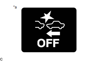
CHECK PRE-COLLISION SYSTEM SENSITIVITY SETTING
(a) Turn the power switch on (IG).
(b)
Operate the steering pad switch assembly to select Change PCS
Sensitivity and check that the warning timing adjustment display on the
multi-information display changes between "Far", "Mid" and "Near"
accordingly.
HINT:
- The pre-collision system warning timing status remains unchanged when
the power switch is turned off and back to ON. This can be changed
through a customize setting using the Techstream.
- The default setting is "Mid".
Parts Location
PARTS LOCATION
ILLUSTRATION
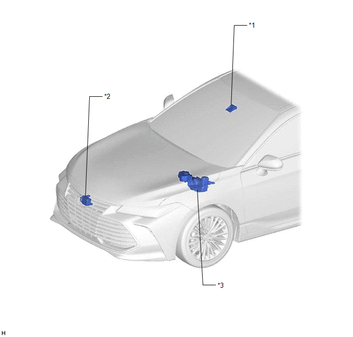
|
*1 | FORWARD RECOGNITION CAMERA |
*2 | MILLIMETER WAVE RADAR SENSOR ASSEMBLY |
|
*3 | BRAKE BOOSTER WITH MASTER CYLINDER ASSEMBLY
- SKID CONTROL ECU | - |
- |
ILLUSTRATION
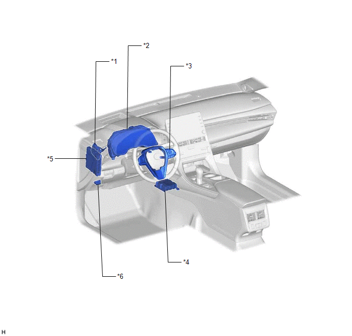
|
*1 | DRIVING SUPPORT ECU ASSEMBLY |
*2 | COMBINATION METER ASSEMBLY
- MULTI-INFORMATION DISPLAY - PCS WARNING LIGHT |
|
*3 | STEERING PAD SWITCH ASSEMBLY |
*4 | AIRBAG ECU ASSEMBLY
- YAW RATE SENSOR |
|
*5 | HYBRID VEHICLE CONTROL ECU |
*6 | DLC3 |
ILLUSTRATION
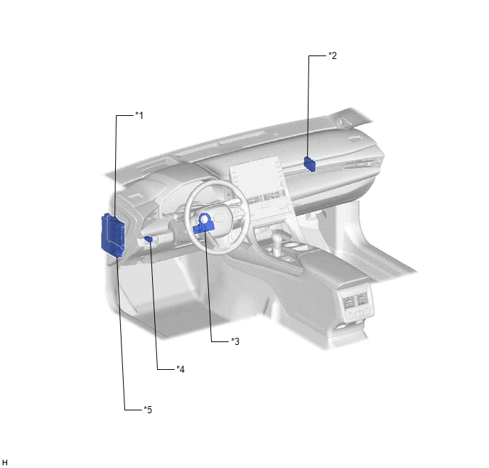
|
*1 | MAIN BODY ECU (MULTIPLEX NETWORK BODY ECU) |
*2 | CENTRAL GATEWAY ECU (NETWORK GATEWAY ECU) |
|
*3 | STEERING SENSOR |
*4 | VSC OFF SWITCH |
|
*5 | INSTRUMENT PANEL JUNCTION BLOCK ASSEMBLY
- ECU IG1 NO. 4 FUSE |
- | - |
Precaution
PRECAUTION
HANDLING PRECAUTION FOR PRE-COLLISION SYSTEM
(a)
In some situations such as the following, the system may determine that
there is a possibility of a frontal collision and operate.
- When passing a vehicle or pedestrian
- When changing lanes while overtaking a preceding vehicle
- When overtaking a preceding vehicle that is changing lanes
- When overtaking a preceding vehicle that is making a left/right turn
- When passing a vehicle in an oncoming lane that is stopped to make a right/left turn
- When driving on a road where relative location to vehicle ahead in an adjacent lane may change, such as on a winding road
- When rapidly closing on a vehicle ahead
- If the front of the vehicle is raised or lowered, such as when the road surface is uneven or undulating
- When approaching objects on the roadside, such as guardrails, utility poles, trees, or walls
- When there is a vehicle, pedestrian, or object by the roadside at the entrance of a curve
- When driving on a narrow path surrounded by a structure, such as in a tunnel or on an iron bridge
- When there is a metal object (manhole cover, steel plate, etc.), steps, or a protrusion on the road surface or roadside
- When a crossing pedestrian approaches very close to the vehicle
- When passing through a place with a low structure above the road (low ceiling, traffic sign, etc.)
- When passing under an object (billboard, etc.) at the top of an uphill road
- When rapidly closing on an electric toll gate barrier, parking area barrier, or other barrier that opens and closes
- When using an automatic car wash
- When driving through or under objects that may contact the vehicle, such as thick grass, tree branches, or a banner
- When the vehicle is hit by water, snow, dust, etc. from a vehicle ahead
- When driving through steam or smoke
- When there are patterns or paint on the road or a wall that may be mistaken for a vehicle or pedestrian
- When driving near an object that reflects radio waves, such as a large truck or guardrail
- When driving near a TV tower, broadcasting station, electric power
plant, or other location where strong radio waves or electrical noise
may be present
(b) In some situations such as the
following, a vehicle may not be detected by the millimeter wave radar
sensor assembly and forward recognition camera, preventing the system
from operating properly.
- If an oncoming vehicle is approaching your vehicle
- If a vehicle ahead is a motorcycle or bicycle
- When approaching the side or front of a vehicle
- If a preceding vehicle has a small rear end, such as an unloaded truck
- If a preceding vehicle has a low rear end, such as a low bed trailer
- If a vehicle ahead is carrying a load which protrudes past its rear bumper
- If a vehicle ahead has extremely high ground clearance
- If a vehicle ahead is irregularly shaped, such as a tractor or side car
- If the sun or other light is shining directly on a vehicle ahead
- If a vehicle cuts in front of your vehicle or emerges from beside a vehicle
- If a vehicle ahead makes an abrupt maneuver (such as sudden swerving, acceleration or deceleration)
- When suddenly cutting behind a preceding vehicle
- When a vehicle ahead is not directly in front of your vehicle
- When driving in inclement weather such as heavy rain, fog, snow or a sandstorm
- When the vehicle is hit by water, snow, dust, etc. from a vehicle ahead
- When driving through steam or smoke
- When driving in a place where the surrounding brightness changes suddenly, such as at the entrance or exit of a tunnel
- When a very bright light, such as the sun or the headlights of oncoming
traffic, shines directly into the forward recognition camera
- When the surrounding area is dim, such as at dawn or dusk, or while at night or in a tunnel
- After the hybrid system has started the vehicle has not been driven for a certain amount of time
- While making a left/right turn and for a few seconds after making a left/right turn
- While driving on a curve and for a few seconds after driving on a curve
- If your vehicle is skidding
- If the front of the vehicle is raised or lowered
- If the wheels are misaligned
- If a wiper blade is blocking the forward recognition camera
- The vehicle is wobbling
- The vehicle is being driven at extremely high speeds
- When driving on a hill
- If the millimeter wave radar sensor assembly or forward recognition camera is misaligned
(c) In some situations such as the
following, sufficient braking force may not be obtained, preventing the
system from performing properly.
- If the braking functions cannot operate to their full extent, such as
when the brake parts are extremely cold, extremely hot, or wet
- If the vehicle is not properly maintained (brakes or tires are excessively worn, improper tire inflation pressure, etc.)
- When the vehicle is being driven on a gravel road or other slippery surface
(d) Some pedestrians such as the
following may not be detected by the millimeter wave radar sensor
assembly and forward recognition camera, preventing the system from
operating properly.
- Pedestrians shorter than approximately 1 m (3.2 ft.) or taller than approximately 2 m (6.5 ft.)
- Pedestrians wearing oversized clothing (a rain coat, long skirt, etc.), making their silhouette obscure
- Pedestrians who are carrying large baggage, holding an umbrella, etc., hiding part of their body
- Pedestrians who are bending forward or squatting
- Pedestrians who are pushing a stroller, wheelchair, bicycle or other vehicle
- Groups of pedestrians which are close together
- Pedestrians who are wearing white and look extremely bright
- Pedestrians in the dark, such as at night or while in a tunnel
- Pedestrians whose clothing appears to be nearly the same color or brightness as their surroundings
- Pedestrians near walls, fences, guardrails, or large objects
- Pedestrians who are on a metal object (manhole cover, steel plate, etc.) on the road
- Pedestrians who are walking fast
- Pedestrians who are changing speed abruptly
- Pedestrians running out from behind a vehicle or a large object
- Pedestrians who are extremely close to the side of the vehicle (outside rear view mirror, etc.)
(e) When the PCS warning light
illuminates and a warning message is displayed on the multi-information
display, the system may not temporarily operate, or it may have a
malfunction.
HINT:
For details on the operation of the PCS warning light and displayed warning messages, refer to Diagnosis System.
Click here 
(1)
In the following situations, the warning light will turn off, the
message will disappear and the system will become operational when
normal operating conditions return.
- When the millimeter wave radar sensor assembly or forward recognition
camera or the area around either sensor is hot, such as in the sun
- When the millimeter wave radar sensor assembly or forward recognition
camera or the area around either sensor is cold, such as in an extremely
cold environment
- When a millimeter wave radar sensor assembly or forward recognition camera is dirty or covered with snow, etc.
- When the part of the windshield glass in front of the forward
recognition camera is fogged up or covered with condensation or ice
- If the forward recognition camera is obstructed, such as when the hood
is open or a sticker is attached to the windshield glass near the
forward recognition camera
- When automatic calibration is being performed after millimeter wave axis misalignment is detected
(f) If VSC is disabled, the pre-collision brake assist and pre-collision braking functions are also disabled.
HINT:
The
PCS warning light will turn on and "VSC Turned Off Pre-collision Brake
System Unavailable" will be displayed on the multi-information display.
PRECAUTION FOR DISCONNECTING CABLE FROM NEGATIVE AUXILIARY BATTERY TERMINAL
NOTICE:
- When disconnecting the cable from the negative (-) auxiliary battery
terminal, initialize the following systems after the cable is
reconnected.
|
System Name |
See Procedure |
|
Lane Departure Alert System (w/ Steering Control) |

|
|
Pre-collision System |
|
Intelligent Clearance Sonar System |
|
Lighting System (w/ Cornering Light) |
|
Parking Assist Monitor System |
|
Panoramic View Monitor System |
- If the auxiliary battery has been discharged and charged or the cable
has been disconnected and reconnected to the negative (-) auxiliary
battery terminal, perform Steering Sensor Zero Point Calibration.
Click here 
PRECAUTION BEFORE SERVICING
(a)
Make sure to turn the pre-collision system off in the following
situations, as it may operate unexpectedly or may not operate when
necessary.
- When the vehicle is being towed
- When the vehicle is towing another vehicle
- When transporting the vehicle via truck, boat, train or similar means of transportation
- When the vehicle is raised on a lift with the hybrid system operating and the tires are allowed to rotate freely
- When inspecting the vehicle using a drum tester such as a chassis
dynamometer or speedometer tester, or when using an on vehicle wheel
balancer
- When a strong impact is applied to the front bumper or front grille, due to an accident or other reasons
- If the vehicle cannot be driven in a stable manner, such as when the vehicle has been in an accident or is malfunctioning
- When the vehicle is driven in a sporty manner or off-road
- When the tires are not properly inflated
- When the tires are very worn
- When tires of a size other than specified are installed
- When tire chains are installed
- When a compact spare tire or an emergency tire puncture repair kit is used
- If equipment (snow plow, etc.) that may obstruct the millimeter wave
radar sensor assembly or forward recognition camera is temporarily
installed to the vehicle
TROUBLESHOOTING PRECAUTIONS
(a)
If a terminal contact malfunction or part installation problem occurs,
removal and reinstallation of the suspected part may return the system
to normal. However, be aware that the normal condition may only be
temporary.
(b) Before disconnecting connectors or
removing/installing parts, determine the malfunctioning area by checking
and writing down the vehicle conditions (output DTCs, etc.) at the time
the malfunction occurred.
(c) Be sure to check for
DTCs related to other systems. The pre-collision system may be
influenced by malfunctions in other systems.
(d)
The pre-collision system uses the CAN communication system. First,
confirm that there are no malfunctions in the CAN communication system.
Refer to How to Proceed with Troubleshooting.
Click here

HANDLING PRECAUTIONS
(a) When removing and installing ECUs, sensors, switches or other pre-collision system related parts, perform the following:
- Make sure that the power switch is off unless otherwise specified in the procedure.
- After removal/installation, check for DTCs and confirm that a normal system code is output.
REPLACEMENT PRECAUTIONS
(a) DRIVING SUPPORT ECU ASSEMBLY:
(1)
When replacing the driving support ECU assembly, always replace it with
a new one. If a driving support ECU assembly which was installed to
another vehicle is used, the information stored in it will not match the
information from the vehicle and a DTC may be stored.
(b) MILLIMETER WAVE RADAR SENSOR ASSEMBLY:
(1)
When replacing the millimeter wave radar sensor assembly, always
replace it with a new one. When a new millimeter wave radar sensor
assembly is installed to the vehicle, it receives vehicle information
from the driving support ECU assembly and stores it. If a millimeter
wave radar sensor assembly which was installed to another vehicle is
used, the information stored in the driving support ECU assembly and
millimeter wave radar sensor assembly will not match and a DTC may be
stored.
(2) If the millimeter wave radar sensor
assembly has been replaced with a new one, be sure to perform Front Beam
Axis Adjustment.
Click here 
(c) FORWARD RECOGNITION CAMERA:
(1)
If the forward recognition camera has been replaced with a new one or
the windshield glass has been removed and installed, it is necessary to
perform forward recognition camera adjustment. If the system is turned
on without performing forward recognition camera adjustment, DTC C1AA9
will be stored.
Click here 
(d) WINDSHIELD GLASS:
(1)
When replacing the windshield glass of a vehicle equipped with a
forward recognition camera, make sure to use a Toyota genuine part. If a
non-Toyota genuine part is used, the forward recognition camera may not
be able to be installed due to a missing bracket or the pre-collision
system may not operate properly due to a difference in the
transmissivity or black ceramic border.
(2) Do not
attach stickers, including transparent stickers, or other items to the
outer side of the windshield glass assembly within the area in front of
the forward recognition camera.
Problem Symptoms Table
PROBLEM SYMPTOMS TABLE
HINT:
- Use the table below to help determine the cause of problem symptoms. If
multiple suspected areas are listed, the potential causes of the
symptoms are listed in order of probability in the "Suspected Area"
column of the table. Check each symptom by checking the suspected areas
in the order they are listed. Replace parts as necessary.
- Inspect the fuses and relays related to this system before inspecting the suspected areas below.
- The pre-collision system uses the CAN communication system. First,
confirm that there are no malfunctions in the CAN communication system.
Refer to How to Proceed with Troubleshooting.
Pre-Collision System |
Symptom | Suspected Area |
Link |
|
"Pre-Collision System Unavailable" is displayed |
History of millimeter wave radar sensor assembly front beam misalignment (vertical)* |
 |
|
Perform millimeter wave radar sensor assembly adjustment |
 |
|
Millimeter wave radar sensor assembly temperature malfunction |
 |
|
Millimeter wave radar sensor assembly low voltage malfunction |
 |
|
Millimeter wave radar sensor assembly |
 |
|
Combination meter assembly |
 |
|
Driving support ECU assembly |
 |
|
"Pre-Collision System Unavailable Clean Sensor" is displayed |
Foreign matter attached to millimeter wave radar sensor assembly |
- |
| Millimeter wave radar sensor assembly |
 |
|
Combination meter assembly |
 |
|
Driving support ECU assembly |
 |
|
"Front Camera Unavailable" is displayed |
Check current condition of forward recognition camera based on related Data List items.
- Abnormal forward recognition camera voltage
- Forward recognition camera temperature outside of operational range
- Other forward recognition camera malfunction
|
 |
|
Forward recognition camera |
 |
|
Combination meter assembly |
 |
|
Driving support ECU assembly |
 |
|
"Front Camera Unavailable Remove Debris On Windshield" is displayed |
Front of forward recognition camera or windshield glass is dirty or misty |
- |
| Forward recognition camera |
 |
|
Combination meter assembly |
 |
|
Driving support ECU assembly |
 |
|
Although
there is possibility of collision, pre-collision controls (all
controls) do not operate ("Pre-collision System Unavailable" is not
displayed) | Check if pre-collision system is canceled |
- |
| Vehicle condition/environment does not match the pre-collision system operation conditions. |
 |
|
Check installation condition of millimeter wave radar sensor assembly |
 |
|
Perform millimeter wave radar sensor assembly adjustment |
 |
|
Millimeter wave radar sensor assembly |
 |
|
Check installation condition of forward recognition camera |
 |
|
Perform forward recognition camera adjustment |
 |
|
Forward recognition camera |
 |
|
Driving support ECU assembly |
 |
|
Although there is no possibility of collision, pre-collision controls (all controls) operate |
Vehicle condition/environment does not match the pre-collision system operation conditions. |
 |
|
Check installation condition of millimeter wave radar sensor assembly |
 |
|
Perform millimeter wave radar sensor assembly adjustment |
 |
|
Millimeter wave radar sensor assembly |
 |
|
Check installation condition of forward recognition camera |
 |
|
Perform forward recognition camera adjustment |
 |
|
Forward recognition camera |
 |
|
Driving support ECU assembly |
 |
|
Pre-collision system does not operate |
Check if pre-collision system is canceled |
- |
| Driving support ECU assembly |
 |
|
Pre-collision system cannot be canceled (PCS warning light does not illuminate) |
Combination meter assembly (check if indicator illuminates using Active Test) |
 |
|
Driving support ECU assembly |
 |
|
Combination meter assembly |
 |
- *: If "Pre-Collision System Unavailable." is displayed on the
multi-information display and there is front beam axis misalignment
(vertical) history, the millimeter wave radar sensor assembly may be
performing beam axis alignment correction. In this case, the message
will disappear when the millimeter wave radar sensor assembly front beam
axis adjustment has completed.
"Pre-Collision System Unavailable." disappears when the
millimeter wave radar sensor assembly beam axis alignment correction
has completed.
Make sure to delete the beam axis
misalignment history when the millimeter wave radar sensor assembly beam
axis alignment correction has completed.
Click here 
System Diagram
SYSTEM DIAGRAM
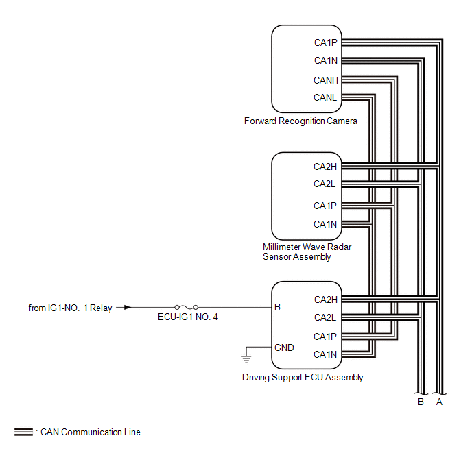
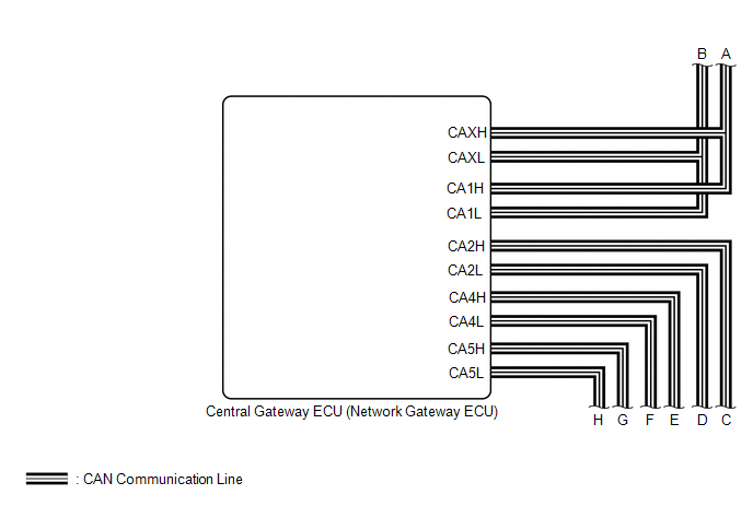
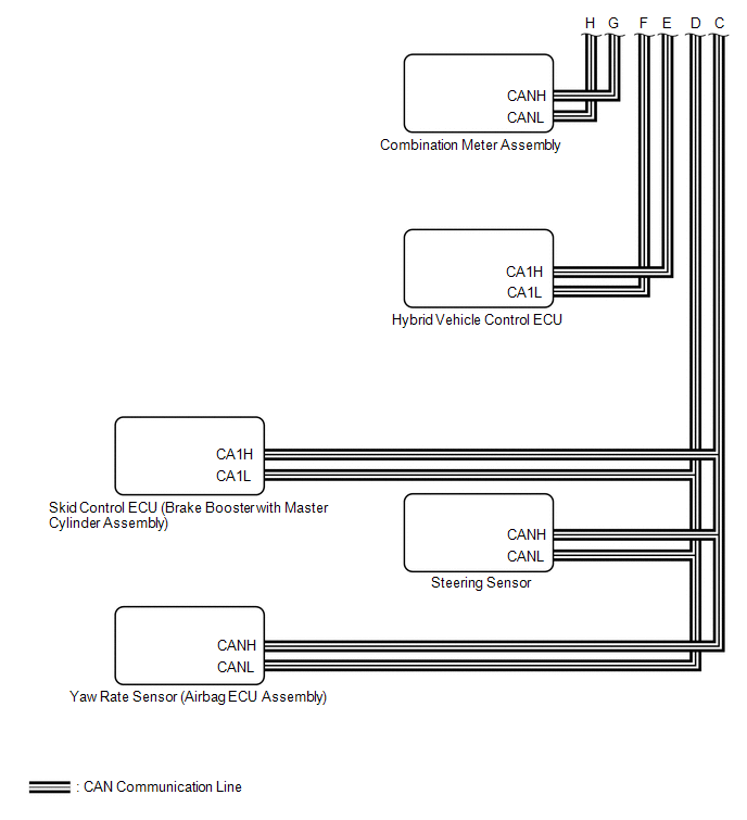 Communication Table
 |
Sender | Receiver |
Signal | Line |
|
Driving Support ECU Assembly | Skid Control ECU (Brake Booster with Master Cylinder Assembly) |
- Brake assist standby signal
- Pre-collision braking operation signal
| CAN |
|
Driving Support ECU Assembly | Combination Meter Assembly |
- Pre-collision system malfunction signal
- Pre-collision system warning distance signal
- Warning signal
- Pre-collision system cancel signal
| CAN |
|
Driving Support ECU Assembly | Forward Recognition Camera |
- Pre-collision warning signal
- Pre-collision braking operation signal
| CAN |
|
Skid Control ECU (Brake Booster with Master Cylinder Assembly) |
Driving Support ECU Assembly |
- Vehicle speed signal
- Stop light switch signal
- Vehicle yaw rate sensor signal
- Electronically controlled brake system operation signal
- Electronically controlled brake system malfunction signal
| CAN |
|
Skid Control ECU (Brake Booster with Master Cylinder Assembly) |
Forward Recognition Camera |
- Vehicle speed signal
- Vehicle yaw rate sensor signal
| CAN |
|
Yaw Rate Sensor (Airbag ECU Assembly) |
Driving Support ECU Assembly | Vehicle yaw rate sensor signal |
CAN |
| Yaw Rate Sensor (Airbag ECU Assembly) |
Forward Recognition Camera | Vehicle yaw rate sensor signal |
CAN |
| Main Body ECU (Multiplex Network Body ECU) |
Driving Support ECU Assembly | Vehicle specification information (destination) |
CAN |
| Main Body ECU (Multiplex Network Body ECU) |
Forward Recognition Camera | Vehicle specification information (destination) |
CAN |
| Steering Sensor |
Driving Support ECU Assembly |
- Steering angle sensor signal
- Steering angle sensor malfunction signal
| CAN |
|
Steering Sensor | Forward Recognition Camera |
Steering angle sensor malfunction signal |
CAN |
| Hybrid Vehicle Control ECU |
Driving Support ECU Assembly |
- Shift position signal (D, R)
- Engine type information signal
- Vehicle specification information (2WD/4WD information)
| CAN |
|
Millimeter Wave Radar Sensor Assembly |
Driving Support ECU Assembly |
- Front obstacle recognition signal
- Distance signal
- Relative speed signal
| CAN |
|
Forward Recognition Camera | Driving Support ECU Assembly |
- Front obstacle recognition signal
- Distance signal
| CAN |
Terminals Of Ecu
TERMINALS OF ECU

CHECK DRIVING SUPPORT ECU ASSEMBLY
(a) Measure the voltage and resistance according to the value(s) in the table below.
|
Terminal No. (Symbol) | Wiring Color |
Terminal Description | Condition |
Specified Condition |
|
G39-7 (B) - G39-28 (GND) |
B - W-B | Power source |
Power switch on (IG) |
11 to 14 V |
|
Power switch off | Below 1 V |
|
G39-28 (GND) - Body ground |
W-B - Body ground | Ground |
Always | Below 1 Ω |
(b) Check for pulses according to the value(s) in the table below.
HINT:
If
the waveform is not similar to that shown in the illustration, a
malfunction of a CAN bus line, terminating resistor, or the driving
support ECU assembly is suspected.
|
Terminal No. (Symbol) | Wiring Color |
Terminal Description | Condition |
Specified Condition |
|
G39-8 (CA1P) - G39-28 (GND) |
G - W-B | CAN communication signal |
Power switch on (IG) |
Pulse generation (See waveform 1) |
|
G39-9 (CA1N) - G39-28 (GND) |
W - W-B | CAN communication signal |
Power switch on (IG) |
Pulse generation (See waveform 2) |
|
G39-10 (CA2H) - G39-28 (GND) |
R - W-B | CAN communication signal |
Power switch on (IG) |
Pulse generation (See waveform 1) |
|
G39-11 (CA2L) - G39-28 (GND) |
W - W-B | CAN communication signal |
Power switch on (IG) |
Pulse generation (See waveform 2) |
(1) WAVEFORM 1
|
Item | Content |
|
Terminal Name | Between G39-8 (CA1P) - G39-28 (GND)
Between G39-10 (CA2H) - G39-28 (GND) |
|
Tester Range | 1 V/DIV., 10 ÎĽsec./DIV. |
|
Condition | Power switch on (IG) |
HINT:
The waveform varies depending on the CAN communication signal.
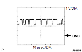
(2) WAVEFORM 2
|
Item | Content |
|
Terminal Name | Between G39-9 (CA1N) - G39-28 (GND)
Between G39-11 (CA2L) - G39-28 (GND) |
|
Tester Range | 1 V/DIV., 10 ÎĽsec./DIV. |
|
Condition | Power switch on (IG) |
HINT:
The waveform varies depending on the CAN communication signal.
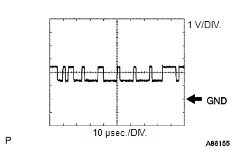

CHECK MILLIMETER WAVE RADAR SENSOR ASSEMBLY
(a) Measure the voltage and resistance according to the value(s) in the table below.
|
Terminal No. (Symbol) | Wiring Color |
Terminal Description | Condition |
Specified Condition |
|
A25-8 (IGB) - A25-1 (SGND) |
R - W-B | Power source |
Power switch on (IG) |
11 to 14 V |
|
A25-1 (SGND) - Body ground |
W-B - Body ground | Ground |
Always | Below 1 Ω |
(b) Check for pulses according to the value(s) in the table below.
HINT:
If
the waveform is not similar to that shown in the illustration, a
malfunction of a CAN bus line, terminating resistor, or the millimeter
wave radar sensor assembly is suspected.
|
Terminal No. (Symbol) | Wiring Color |
Terminal Description | Condition |
Specified Condition |
|
A25-3 (CA2H) - A25-1 (SGND) |
R - W-B | CAN communication signal |
Power switch on (IG) |
Pulse generation (See waveform 1) |
|
A25-2 (CA2L) - A25-1 (SGND) |
W - W-B | CAN communication signal |
Power switch on (IG) |
Pulse generation (See waveform 2) |
|
A25-5 (CA1P) - A25-1 (SGND) |
G - W-B | CAN communication signal |
Power switch on (IG) |
Pulse generation (See waveform 1) |
|
A25-6 (CA1N) - A25-1 (SGND) |
W - W-B | CAN communication signal |
Power switch on (IG) |
Pulse generation (See waveform 2) |
(1) WAVEFORM 1
|
Item | Content |
|
Terminal Name | Between A25-3 (CA2H) and A25-1 (SGND)
Between A25-5 (CA1P) and A25-1 (SGND) |
|
Tester Range | 1 V/DIV., 10 ÎĽsec./DIV. |
|
Condition | Power switch on (IG) |
HINT:
The waveform varies depending on the CAN communication signal.

(2) WAVEFORM 2
|
Item | Content |
|
Terminal Name | Between A25-2 (CA2L) and A25-1 (SGND)
Between A25-6 (CA1N) and A25-1 (SGND) |
|
Tester Range | 1 V/DIV., 10 ÎĽsec./DIV. |
|
Condition | Power switch on (IG) |
HINT:
The waveform varies depending on the CAN communication signal.

Lost Communication with Front Camera Module (U023A)
DESCRIPTION
|
DTC No. | Detection Item |
DTC Detection Condition | Trouble Area |
|
U023A | Lost Communication with Front Camera Module |
When
the power switch is on (IG), a communication error between the forward
recognition camera and driving support ECU assembly is detected for
approximately 3 seconds. |
- CAN communication system
- CAN bus line
- Forward recognition camera
|
WIRING DIAGRAM
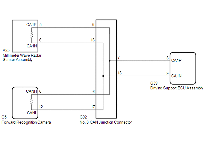
CAUTION / NOTICE / HINT
NOTICE:
- Inspect the fuses for circuits related to this system before performing the following procedure.
- Before measuring the resistance of the CAN bus, turn the power switch
off and leave the vehicle for 1 minute or more without operating the key
or any switches, or opening or closing the doors. After that,
disconnect the cable from the negative (-) auxiliary battery terminal
and leave the vehicle for 1 minute or more before measuring the
resistance.
- After turning the power switch off, waiting time may be required before
disconnecting the cable from the negative (-) auxiliary battery
terminal. Therefore, make sure to read the disconnecting the cable from
the negative (-) auxiliary battery terminal notices before proceeding
with work.
Click here 
- When replacing the forward recognition camera, always replace it with a
new one. If a forward recognition camera which was installed to another
vehicle is used, the information stored in the forward recognition
camera will not match the information from the vehicle. As a result, a
DTC may be stored.
- If the forward recognition camera has been replaced with a new one, be sure to perform forward recognition camera adjustment.
Click here 
HINT:
- Operating the power switch, any other switches or a door triggers
related ECU and sensor communication on the CAN. This communication will
cause the resistance value to change.
- Even after DTCs are cleared, if a DTC is stored again after driving the
vehicle for a while, the malfunction may be occurring due to vibration
of the vehicle. In such a case, wiggling the connectors of ECUs or wire
harnesses while performing the inspection below may help determine the
cause of the malfunction.
PROCEDURE
|
1. | READ VALUE USING TECHSTREAM (CAN BUS CHECK) |
(a) Connect the Techstream to the DLC3.
(b) Turn the power switch to ON.
(c) Turn the Techstream on.
(d) Enter the following menus: System Select / Can Bus Check.
Click here 
CAN Bus Check
|
Result | Proceed to |
|
All of the ECUs and sensors that are currently connected to the CAN communication system are displayed |
A |
| None
of the ECUs and sensors that are currently connected to the CAN
communication system are displayed, or some of them are not displayed |
B |
| B |
 | GO TO CAN COMMUNICATION SYSTEM |
|
A |
 | |
(a) Check for DTCs.
Body Electrical > Pre-Collision 2 > Trouble Codes
|
Result | Proceed to |
|
DTC U1002 is not output |
A |
| DTC U1002 is output |
B |
| B |
 | GO TO DTC CHART (U1002) |
|
A |
 | |
| 3. |
CHECK FOR OPEN IN CAN BUS MAIN LINES (FORWARD RECOGNITION CAMERA) |
(a) Disconnect the cable from the negative (-) auxiliary battery terminal.
| (b) Disconnect the O5 forward recognition camera connector. |
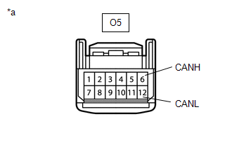 |
|
*a | Front view of wire harness connector
(to Forward Recognition Camera) | | |
(c) Measure the resistance according to the value(s) in the table below.
Standard Resistance:
|
Tester Connection | Condition |
Specified Condition |
|
O5-6 (CANH) - O5-12 (CANL) |
Cable disconnected from negative (-) auxiliary battery terminal |
108 to 132 Ω |
(d) Connect the O5 forward recognition camera connector.
| OK |
 | REPLACE FORWARD RECOGNITION CAMERA |
| NG |
 | REPAIR OR REPLACE CAN BUS MAIN LINE OR CONNECTOR (NO. 8 CAN JUNCTION CONNECTOR - FORWARD RECOGNITION CAMERA) |
Lost Communication with Yaw Rate Sensor Module (U0125,U0126,U0129,U0155,U0293)
DESCRIPTION
The driving
support ECU assembly uses the millimeter wave radar sensor assembly to
detect objects in front of the vehicle. Based on signals from the
millimeter wave radar sensor assembly, the driving support ECU assembly
sends pre-collision system control operation signals. These DTCs are
stored when a communication malfunction occurs between ECUs that perform
pre-collision system control.
|
DTC No. | Detection Item |
DTC Detection Condition | Trouble Area |
|
U0125 | Lost Communication with Yaw Rate Sensor Module |
When
the power switch is on (IG), a communication error between the yaw rate
sensor (airbag ECU assembly) and the driving support ECU assembly is
detected for approximately 1 second. |
CAN communication system |
|
U0126 | Lost Communication with Steering Angle Sensor Module |
When
the power switch is on (IG), a communication error between the steering
sensor and the driving support ECU assembly is detected for
approximately 4 seconds. | CAN communication system |
|
U0129 | Lost Communication with Brake System Control Module |
When
the power switch is on (IG), a communication error between the skid
control ECU (brake booster with master cylinder assembly) and the
driving support ECU assembly is detected for approximately 3 seconds. |
CAN communication system |
|
U0155 | Lost Communication with Instrument Panel Cluster (IPC) Control Module |
When
the power switch is on (IG), a communication error between the
combination meter assembly and the driving support ECU assembly is
detected for approximately 3 seconds. |
CAN communication system |
|
U0293 | Lost Communication with HV ECU |
When
the vehicle is being driven at a speed of 5 km/h (4 mph) or more, a
communication error between the hybrid vehicle control ECU and the
driving support ECU assembly is detected for approximately 5 seconds. |
CAN communication system |
PROCEDURE
(a) Clear the DTCs.
Body Electrical > Pre-Collision 2 > Clear DTCs
(b) Make sure that the DTC detection conditions are met.
HINT:
If the detection conditions are not met, the system cannot detect the malfunction.
(c) Check for DTCs.
Body Electrical > Pre-Collision 2 > Trouble Codes
|
Result | Proceed to |
|
DTC U0125, U0126, U0129, U0155 and U0293 are not output |
A |
| DTC U0125, U0126, U0129, U0155 or U0293 is output |
B |
| A |
 | USE SIMULATION METHOD TO CHECK |
| B |
 | GO TO CAN COMMUNICATION SYSTEM |
Lost Communication with Cruise Control Front Distance Range Sensor (U0235)
DESCRIPTION
|
DTC No. | Detection Item |
DTC Detection Condition | Trouble Area |
|
U0235 | Lost Communication with Cruise Control Front Distance Range Sensor |
When
the power switch is on (IG), a communication error between the
millimeter wave radar sensor assembly and the driving support ECU
assembly is detected for approximately 1 second. |
- CAN communication system
- CAN bus line
- Millimeter wave radar sensor assembly
- Driving support ECU assembly
|
WIRING DIAGRAM
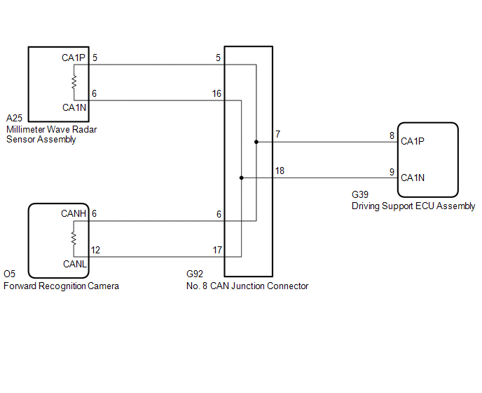
CAUTION / NOTICE / HINT
NOTICE:
- Inspect the fuses for circuits related to this system before performing the following procedure.
- Before measuring the resistance of the CAN bus, turn the power switch
off and leave the vehicle for 1 minute or more without operating the key
or any switches, or opening or closing the doors. After that,
disconnect the cable from the negative (-) auxiliary battery terminal
and leave the vehicle for 1 minute or more before measuring the
resistance.
- After turning the power switch off, waiting time may be required before
disconnecting the cable from the negative (-) auxiliary battery
terminal. Therefore, make sure to read the disconnecting the cable from
the negative (-) auxiliary battery terminal notices before proceeding
with work.
Click here 
- When replacing the driving support ECU assembly, always replace it with a
new one. If a driving support ECU assembly which was installed to
another vehicle is used, the information stored in the driving support
ECU assembly will not match the information from the vehicle. As a
result, a DTC may be stored.
- When replacing the millimeter wave radar sensor assembly, always replace
it with a new one. If a millimeter wave radar sensor assembly which was
installed to another vehicle is used, the information stored in the
millimeter wave radar sensor assembly will not match the information
from the vehicle. As a result, a DTC may be stored.
- When the millimeter wave radar sensor assembly is replaced with a new
one, adjustment of the radar sensor beam axis must be performed.
Click here 
HINT:
- Operating the power switch, any other switches or a door triggers
related ECUs and sensors to communicate using the CAN communication
system. This communication will cause the resistance value to change.
- Even after DTCs are cleared, if a DTC is stored again after driving the
vehicle for a while, the malfunction may be occurring due to vibration
of the vehicle. In such a case, wiggling the connectors of ECUs or wire
harnesses while performing the inspection below may help determine the
cause of the malfunction.
PROCEDURE
|
1. | READ VALUE USING TECHSTREAM (CAN BUS CHECK) |
(a) Connect the Techstream to the DLC3.
(b) Turn the power switch to ON.
(c) Turn the Techstream on.
(d) Enter the following menus: System Select / Can Bus Check.
Click here 
CAN Bus Check
|
Result | Proceed to |
|
All of the ECUs and sensors that are currently connected to the CAN communication system are displayed |
A |
| None
of the ECUs and sensors that are currently connected to the CAN
communication system are displayed, or some of them are not displayed |
B |
| B |
 | GO TO CAN COMMUNICATION SYSTEM |
|
A |
 | |
(a) Check for DTCs.
Body Electrical > Pre-Collision 2 > Trouble Codes
|
Result | Proceed to |
|
DTC U1002 is not output |
A |
| DTC U1002 is output |
B |
| B |
 | GO TO DTC CHART (U1002) |
|
A |
 | |
| 3. |
CHECK FOR OPEN IN CAN BUS MAIN LINES (MILLIMETER WAVE RADAR SENSOR ASSEMBLY) |
(a) Disconnect the cable from the negative (-) auxiliary battery terminal.
| (b) Disconnect the A25 millimeter wave radar sensor assembly connector. |
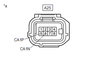 |
|
*a | Front view of wire harness connector
(to Millimeter Wave Radar Sensor Assembly) | | |
(c) Measure the resistance according to the value(s) in the table below.
Standard Resistance:
|
Tester Connection | Condition |
Specified Condition |
|
A25-5 (CA1P) - A25-6 (CA1N) |
Cable disconnected from negative (-) auxiliary battery terminal |
108 to 132 Ω |
(d) Connect the A25 millimeter wave radar sensor assembly connector.
| NG |
 | REPAIR OR REPLACE CAN BUS MAIN LINE OR CONNECTOR (NO. 8 CAN JUNCTION CONNECTOR - MILLIMETER WAVE RADAR SENSOR ASSEMBLY) |
|
OK |
 | |
(a) Check for DTCs.
Chassis > Front Recognition Camera > Trouble Codes
|
Result | Proceed to |
|
DTC U0235 is not output |
A |
| DTC U0235 is output |
B |
| A |
 | REPLACE DRIVING SUPPORT ECU ASSEMBLY |
| B |
 | REPLACE MILLIMETER WAVE RADAR SENSOR ASSEMBLY |
Lost Communication with Gateway Module (U1002)
DESCRIPTION
This DTC is
stored when the driving support ECU assembly cannot receive signals from
the forward recognition camera or millimeter wave radar sensor
assembly.
|
DTC No. | Detection Item |
DTC Detection Condition | Trouble Area |
|
U1002 | Lost Communication with Gateway Module |
After
the power switch is turned on, communication between the driving
support ECU assembly and any of the following components is abnormal for
2 seconds or more
- Forward recognition camera
- Millimeter wave radar sensor assembly
|
- CAN bus main line, CAN bus branch line or connector
- Forward recognition camera
- Millimeter wave radar sensor assembly
- Driving support ECU assembly
- No. 8 CAN junction connector
|
WIRING DIAGRAM
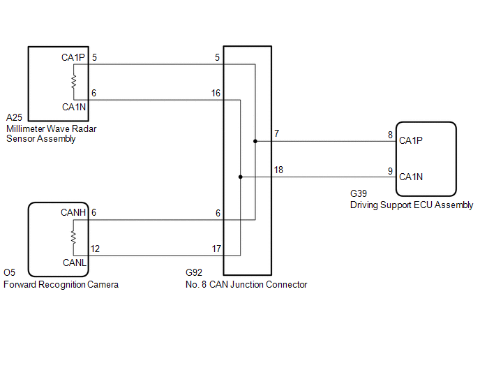
CAUTION / NOTICE / HINT
NOTICE:
- Before measuring the resistance of the CAN bus, turn the power switch
off and leave the vehicle for 1 minute or more without operating the key
or any switches, or opening or closing the doors. After that,
disconnect the cable from the negative (-) auxiliary battery terminal
and leave the vehicle for 1 minute or more before measuring the
resistance.
- After turning the power switch off, waiting time may be required before
disconnecting the cable from the negative (-) auxiliary battery
terminal. Therefore, make sure to read the disconnecting the cable from
the negative (-) auxiliary battery terminal notices before proceeding
with work.
Click here 
- When replacing the millimeter wave radar sensor assembly, always replace
it with a new one. If a millimeter wave radar sensor assembly which was
installed to another vehicle is used, the information stored in the
millimeter wave radar sensor assembly will not match the information
from the vehicle. As a result, a DTC may be stored.
- When the millimeter wave radar sensor assembly is replaced with a new
one, adjustment of the radar sensor beam axis must be performed.
Click here 
- When replacing the forward recognition camera, always replace it with a
new one. If a forward recognition camera which was installed to another
vehicle is used, the information stored in the forward recognition
camera will not match the information from the vehicle. As a result, a
DTC may be stored.
- If the forward recognition camera has been replaced with a new one, be sure to perform forward recognition camera adjustment.
Click here 
HINT:
- Operating the power switch, any other switches or a door triggers
related ECU and sensor communication on the CAN. This communication will
cause the resistance value to change.
- Even after DTCs are cleared, if a DTC is stored again after driving the
vehicle for a while, the malfunction may be occurring due to vibration
of the vehicle. In such a case, wiggling the ECUs or wire harness while
performing the inspection below may help determine the cause of the
malfunction.
PROCEDURE
|
1. | CHECK CAN BUS LINE (MALFUNCTION CONFIRMATION) |
(a) Turn the power switch off.
(b) Disconnect the cable from the negative (-) auxiliary battery terminal.
| (c) Measure the resistance according to the value(s) in the table below.
Standard Resistance: |
Tester Connection | Condition |
Specified Condition | Result | |
G39-8 (CA1P) - G39-9 (CA1N) |
Cable disconnected from negative (-) auxiliary battery terminal |
54 to 69 Ω | Below 54 Ω:
Short circuit between bus lines | |
70 Ω or more: Open circuit in a main bus line or driving support ECU assembly branch line | |
G39-8 (CA1P) - G39-28 (GND) |
Cable disconnected from negative (-) auxiliary battery terminal |
200 Ω or higher | Below 200 Ω:
Ground short | |
G39-9 (CA1N) - G39-28 (GND) |
Cable disconnected from negative (-) auxiliary battery terminal |
200 Ω or higher | Below 200 Ω:
Ground short | |
G39-8 (CA1P) - G39-7 (B) |
Cable disconnected from negative (-) auxiliary battery terminal |
6 kΩ or higher | Below 6 kΩ:
+B short | |
G39-9 (CA1N) - G39-7 (B) |
Cable disconnected from negative (-) auxiliary battery terminal |
6 kΩ or higher | Below 6 kΩ:
+B short | |
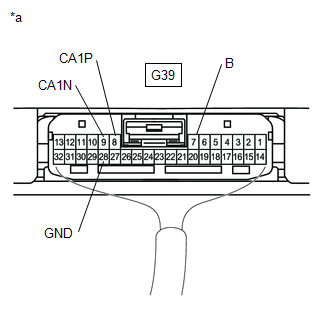 |
|
*a | Component with harness connected
(Driving Support ECU Assembly) | | |
|
Result | Proceed to |
|
OK | A |
|
NG (Open circuit in main line or Driving support ECU assembly branch line) |
B |
| NG (Short circuit between main lines) |
C |
| NG (Short to +B or ground) |
D |
| B |
 | GO TO STEP 3 |
| C |
 | GO TO STEP 8 |
| D |
 | GO TO STEP 12 |
|
A |
 | |
(a) Clear the DTCs.
Body Electrical > Pre-Collision 2 > Clear DTCs
(b) Make sure that the DTC detection conditions are met.
HINT:
If the detection conditions are not met, the system cannot detect the malfunction.
(c) Check for DTCs.
Body Electrical > Pre-Collision 2 > Trouble Codes
|
Result | Proceed to |
|
DTC U1002 is not output |
A |
| DTC U1002 is output |
B |
| A |
 | USE SIMULATION METHOD TO CHECK |
| B |
 | REPLACE DRIVING SUPPORT ECU ASSEMBLY |
| 3. |
CHECK FOR OPEN IN CAN BUS BRANCH LINES (DRIVING SUPPORT ECU ASSEMBLY) |
| (a) Disconnect the G39 driving support ECU assembly connector. |
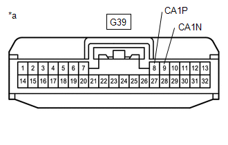 |
|
*a | Front view of wire harness connector
(to Driving Support ECU Assembly) | | |
(b) Measure the resistance according to the value(s) in the table below.
Standard Resistance:
|
Tester Connection | Condition |
Specified Condition |
|
G39-8 (CA1P) - G39-9 (CA1N) |
Cable disconnected from negative (-) auxiliary battery terminal |
108 to 132 Ω |
HINT:
If
the resistance is between 108 and 132 Ω, there may be an open in a CAN
bus main line. If the value is 132 Ω or more, there may be an open in a
CAN bus branch line between the No. 8 CAN junction connector and the
driving support ECU assembly or a connector may be disconnected.
(c) Connect the G39 driving support ECU assembly connector.
| NG |
 | GO TO STEP 7 |
|
OK |
 | |
| 4. |
CHECK FOR OPEN IN CAN BUS MAIN LINES (NO. 8 CAN JUNCTION CONNECTOR) |
| (a) Disconnect the G92 No. 8 CAN junction connector. |
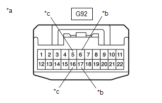 |
|
*a | Front view of wire harness connector
(to No. 8 CAN Junction Connector) | |
*b | to Forward Recognition Camera | |
*c | to Millimeter Wave Radar Sensor Assembly | | |
(b) Measure the resistance according to the value(s) in the table below.
Standard Resistance:
|
Tester Connection | Condition |
Specified Condition | Connected to |
|
G92-6 - G92-17 | Cable disconnected from negative (-) auxiliary battery terminal |
108 to 132 Ω | Forward Recognition Camera |
|
G92-5 - G92-16 | Cable disconnected from negative (-) auxiliary battery terminal |
108 to 132 Ω | Millimeter Wave Radar Sensor Assembly |
(c) Connect the G92 No. 8 CAN junction connector.
|
Result | Proceed to |
|
OK | A |
|
NG (Forward Recognition Camera Main Line) |
B |
| NG (Millimeter Wave Radar Sensor Assembly Main Line) |
C |
| A |
 | REPLACE NO. 8 CAN JUNCTION CONNECTOR |
| C |
 | GO TO STEP 6 |
|
B |
 | |
| 5. |
CHECK FOR OPEN IN CAN BUS MAIN LINES (FORWARD RECOGNITION CAMERA) |
| (a) Disconnect the O5 forward recognition camera connector. |
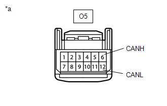 |
|
*a | Front view of wire harness connector
(to Forward Recognition Camera) | | |
(b) Measure the resistance according to the value(s) in the table below.
Standard Resistance:
|
Tester Connection | Condition |
Specified Condition |
|
O5-6 (CANH) - O5-12 (CANL) |
Cable disconnected from negative (-) auxiliary battery terminal |
108 to 132 Ω |
(c) Connect the O5 forward recognition camera connector.
| OK |
 | REPLACE FORWARD RECOGNITION CAMERA |
| NG |
 | REPAIR OR REPLACE CAN BUS MAIN LINE OR CONNECTOR (NO. 8 CAN JUNCTION CONNECTOR - FORWARD RECOGNITION CAMERA) |
| 6. |
CHECK FOR OPEN IN CAN BUS MAIN LINES (MILLIMETER WAVE RADAR SENSOR ASSEMBLY) |
| (a) Disconnect the A25 millimeter wave radar sensor assembly connector. |
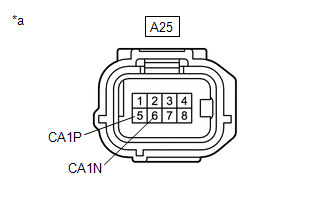 |
|
*a | Front view of wire harness connector
(to Millimeter Wave Radar Sensor Assembly) | | |
(b) Measure the resistance according to the value(s) in the table below.
Standard Resistance:
|
Tester Connection | Condition |
Specified Condition |
|
A25-5 (CA1P) - A25-6 (CA1N) |
Cable disconnected from negative (-) auxiliary battery terminal |
108 to 132 Ω |
(c) Connect the A25 millimeter wave radar sensor assembly connector.
| OK |
 | REPLACE MILLIMETER WAVE RADAR SENSOR ASSEMBLY |
| NG |
 | REPAIR OR REPLACE CAN BUS MAIN LINE OR CONNECTOR (NO. 8 CAN JUNCTION CONNECTOR - MILLIMETER WAVE RADAR SENSOR ASSEMBLY) |
| 7. |
CHECK FOR OPEN IN CAN BUS BRANCH LINES (NO. 8 CAN JUNCTION CONNECTOR - DRIVING SUPPORT ECU ASSEMBLY) |
| (a) Disconnect the G39 driving support ECU assembly connector. |
 |
|
*a | Front view of wire harness connector
(to Driving Support ECU Assembly) | | |
| (b) Disconnect the G92 No. 8 CAN junction connector. |
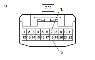 |
|
*a | Front view of wire harness connector
(to No. 8 CAN Junction Connector) | |
*b | to Driving Support ECU Assembly | | |
(c) Measure the resistance according to the value(s) in the table below.
Standard Resistance:
|
Tester Connection | Condition |
Specified Condition |
|
G92-7 - G39-8 (CA1P) |
Cable disconnected from negative (-) auxiliary battery terminal |
Below 1 Ω |
|
G92-18 - G39-9 (CA1N) |
Cable disconnected from negative (-) auxiliary battery terminal |
Below 1 Ω |
(d) Connect the G92 No. 8 CAN junction connector.
(e) Connect the G39 driving support ECU assembly connector.
| OK |
 | REPLACE NO. 8 CAN JUNCTION CONNECTOR |
| NG |
 | REPAIR OR REPLACE CAN BUS BRANCH WIRE (NO. 8 CAN JUNCTION CONNECTOR - DRIVING SUPPORT ECU ASSEMBLY) |
| 8. |
CHECK FOR SHORT BETWEEN CAN BUS LINES (FORWARD RECOGNITION CAMERA) |
| (a) Disconnect the O5 forward recognition camera connector. |
 |
|
*a | Front view of wire harness connector
(to Forward Recognition Camera) | | |
(b) Measure the resistance according to the value(s) in the table below.
Standard Resistance:
|
Tester Connection | Condition |
Specified Condition |
|
O5-6 (CANH) - O5-12 (CANL) |
Cable disconnected from negative (-) auxiliary battery terminal |
108 to 132 Ω |
(c) Connect the O5 forward recognition camera connector.
| OK |
 | REPLACE FORWARD RECOGNITION CAMERA |
|
NG |
 | |
| 9. |
CHECK FOR SHORT BETWEEN CAN BUS LINES (NO. 8 CAN JUNCTION CONNECTOR) |
| (a) Disconnect the G92 No. 8 CAN junction connector. |
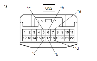 |
|
*a | Front view of wire harness connector
(to No. 8 CAN Junction Connector) | |
*b | to Forward Recognition Camera | |
*c | to Millimeter Wave Radar Sensor Assembly | |
*d | to Driving Support ECU Assembly | | |
(b) Measure the resistance according to the value(s) in the table below.
Standard Resistance:
|
Tester Connection | Condition |
Specified Condition | Connected to |
|
G92-6 - G92-17 | Cable disconnected from negative (-) auxiliary battery terminal |
108 to 132 Ω | Forward Recognition Camera |
|
G92-5 - G92-16 | Cable disconnected from negative (-) auxiliary battery terminal |
108 to 132 Ω | Millimeter Wave Radar Sensor Assembly |
|
G92-7 - G92-18 | Cable disconnected from negative (-) auxiliary battery terminal |
200 Ω or higher | Driving Support ECU Assembly |
(c) Connect the G92 No. 8 CAN junction connector.
|
Result | Proceed to |
|
OK | A |
|
NG (Forward Recognition Camera Main Line) |
B |
| NG (Millimeter Wave Radar Sensor Assembly Main Line) |
C |
| NG (Driving Support ECU Assembly Branch Line) |
D |
| A |
 | REPLACE NO. 8 CAN JUNCTION CONNECTOR |
| B |
 | REPAIR OR REPLACE CAN BUS MAIN LINE OR CONNECTOR (NO. 8 CAN JUNCTION CONNECTOR - FORWARD RECOGNITION CAMERA) |
| D |
 | GO TO STEP 11 |
|
C |
 | |
| 10. |
CHECK FOR SHORT BETWEEN CAN BUS LINES (MILLIMETER WAVE RADAR SENSOR ASSEMBLY) |
| (a) Disconnect the A25 millimeter wave radar sensor assembly connector. |
 |
|
*a | Front view of wire harness connector
(to Millimeter Wave Radar Sensor Assembly) | | |
(b) Measure the resistance according to the value(s) in the table below.
Standard Resistance:
|
Tester Connection | Condition |
Specified Condition |
|
A25-5 (CA1P) - A25-6 (CA1N) |
Cable disconnected from negative (-) auxiliary battery terminal |
108 to 132 Ω |
(c) Connect the A25 millimeter wave radar sensor assembly connector.
| OK |
 | REPLACE MILLIMETER WAVE RADAR SENSOR ASSEMBLY |
| NG |
 | REPAIR OR REPLACE CAN BUS MAIN LINE OR CONNECTOR (NO. 8 CAN JUNCTION CONNECTOR - MILLIMETER WAVE RADAR SENSOR ASSEMBLY) |
| 11. |
CHECK FOR SHORT BETWEEN CAN BUS LINES (DRIVING SUPPORT ECU ASSEMBLY) |
| (a) Disconnect the G39 driving support ECU assembly connector. |
 |
|
*a | Front view of wire harness connector
(to Driving Support ECU Assembly) | | |
(b) Measure the resistance according to the value(s) in the table below.
Standard Resistance:
|
Tester Connection | Condition |
Specified Condition |
|
G39-8 (CA1P) - G39-9 (CA1N) |
Cable disconnected from negative (-) auxiliary battery terminal |
54 to 69 Ω |
(c) Connect the G39 driving support ECU assembly connector.
| OK |
 | REPLACE DRIVING SUPPORT ECU ASSEMBLY |
| NG |
 | REPAIR OR REPLACE CAN BUS BRANCH LINE OR CONNECTOR (NO. 8 CAN JUNCTION CONNECTOR - DRIVING SUPPORT ECU ASSEMBLY) |
| 12. |
CHECK FOR SHORT IN CAN BUS LINE (FORWARD RECOGNITION CAMERA) |
(a) Disconnect the O5 forward recognition camera connector.
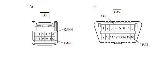
|
*1 | DLC3 |
- | - |
|
*a | Front view of wire harness connector
(to Forward Recognition Camera) |
- | - |
(b) Measure the resistance according to the value(s) in the table below.
Standard Resistance:
|
Tester Connection | Condition |
Specified Condition |
|
O5-6 (CANH) - G45-4 (CG) |
Cable disconnected from negative (-) auxiliary battery terminal |
200 Ω or higher |
|
O5-12 (CANL) - G45-4 (CG) |
Cable disconnected from negative (-) auxiliary battery terminal |
200 Ω or higher |
|
O5-6 (CANH) - G45-16 (BAT) |
Cable disconnected from negative (-) auxiliary battery terminal |
6 kΩ or higher |
|
O5-12 (CANL) - G45-16 (BAT) |
Cable disconnected from negative (-) auxiliary battery terminal |
6 kΩ or higher |
(c) Connect the O5 forward recognition camera connector.
| OK |
 | REPLACE FORWARD RECOGNITION CAMERA |
|
NG |
 | |
| 13. |
CHECK FOR SHORT IN CAN BUS LINE (NO. 8 CAN JUNCTION CONNECTOR) |
(a) Disconnect the G92 No. 8 CAN junction connector.
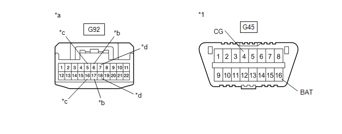
|
*1 | DLC3 |
- | - |
|
*a | Front view of wire harness connector
(to No. 8 CAN Junction Connector) |
*b | to Forward Recognition Camera |
|
*c | to Millimeter Wave Radar Sensor Assembly |
*d | to Driving Support ECU Assembly |
(b) Measure the resistance according to the value(s) in the table below.
Standard Resistance:
|
Tester Connection | Condition |
Specified Condition | Connected to |
|
G92-6 - G45-4 (CG) |
Cable disconnected from negative (-) auxiliary battery terminal |
200 Ω or higher |
Forward Recognition Camera |
|
G92-17 - G45-4 (CG) |
|
G92-6 - G45-16 (BAT) |
6 kΩ or higher |
|
G92-17 - G45-16 (BAT) |
|
G92-5 - G45-4 (CG) |
Cable disconnected from negative (-) auxiliary battery terminal |
200 Ω or higher |
Millimeter Wave Radar Sensor Assembly |
|
G92-16 - G45-4 (CG) |
|
G92-5 - G45-16 (BAT) |
6 kΩ or higher |
|
G92-16 - G45-16 (BAT) |
|
G92-7 - G45-4 (CG) |
Cable disconnected from negative (-) auxiliary battery terminal |
200 Ω or higher |
Driving Support ECU Assembly |
|
G92-18 - G45-4 (CG) |
|
G92-7 - G45-16 (BAT) |
6 kΩ or higher |
|
G92-18 - G45-16 (BAT) |
(c) Connect the G92 No. 8 CAN junction connector.
|
Result | Proceed to |
|
OK | A |
|
NG (Forward Recognition Camera Main Line) |
B |
| NG (Millimeter Wave Radar Sensor Assembly Main Line) |
C |
| NG (Driving Support ECU Assembly Branch Line) |
D |
| A |
 | REPLACE NO. 8 CAN JUNCTION CONNECTOR |
| B |
 | REPAIR OR REPLACE CAN BUS MAIN LINE OR CONNECTOR (NO. 8 CAN JUNCTION CONNECTOR - FORWARD RECOGNITION CAMERA) |
| D |
 | GO TO STEP 15 |
|
C |
 | |
| 14. |
CHECK FOR SHORT IN CAN BUS LINE (MILLIMETER WAVE RADAR SENSOR ASSEMBLY) |
(a) Disconnect the A25 millimeter wave radar sensor assembly connector.
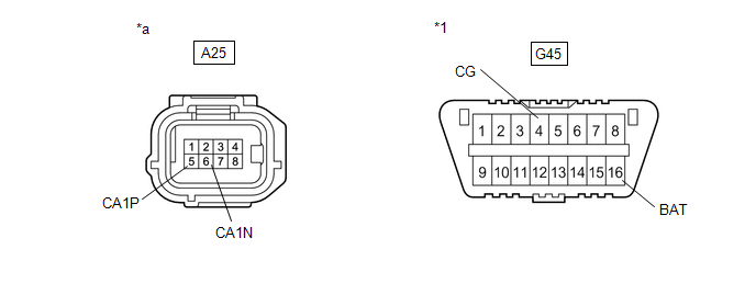
|
*1 | DLC3 |
- | - |
|
*a | Front view of wire harness connector
(to Millimeter Wave Radar Sensor Assembly) |
- | - |
(b) Measure the resistance according to the value(s) in the table below.
Standard Resistance:
|
Tester Connection | Condition |
Specified Condition |
|
A25-5 (CA1P) - G45-4 (CG) |
Cable disconnected from negative (-) auxiliary battery terminal |
200 Ω or higher |
|
A25-6 (CA1N) - G45-4 (CG) |
Cable disconnected from negative (-) auxiliary battery terminal |
200 Ω or higher |
|
A25-5 (CA1P) - G45-16 (BAT) |
Cable disconnected from negative (-) auxiliary battery terminal |
6 kΩ or higher |
|
A25-6 (CA1N) - G45-16 (BAT) |
Cable disconnected from negative (-) auxiliary battery terminal |
6 kΩ or higher |
(c) Connect the A25 millimeter wave radar sensor assembly connector.
| OK |
 | REPLACE MILLIMETER WAVE RADAR SENSOR ASSEMBLY |
| NG |
 | REPAIR OR REPLACE CAN BUS MAIN LINE OR CONNECTOR (NO. 8 CAN JUNCTION CONNECTOR - MILLIMETER WAVE RADAR SENSOR ASSEMBLY) |
| 15. |
CHECK FOR SHORT IN CAN BUS LINE (DRIVING SUPPORT ECU ASSEMBLY) |
(a) Disconnect the G39 driving support ECU assembly connector.
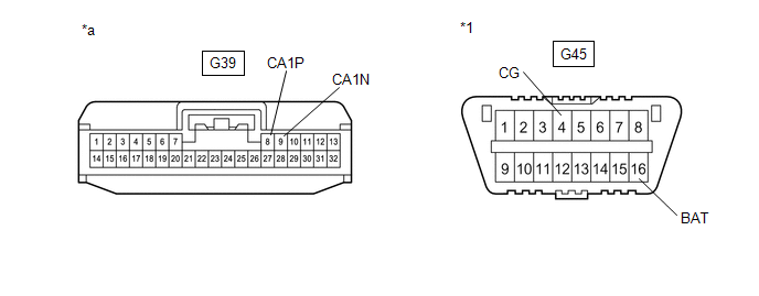
|
*1 | DLC3 |
- | - |
|
*a | Front view of wire harness connector
(to Driving Support ECU Assembly) |
- | - |
(b) Measure the resistance according to the value(s) in the table below.
Standard Resistance:
|
Tester Connection | Condition |
Specified Condition |
|
G39-8 (CA1P) - G45-4 (CG) |
Cable disconnected from negative (-) auxiliary battery terminal |
200 Ω or higher |
|
G39-9 (CA1N) - G45-4 (CG) |
Cable disconnected from negative (-) auxiliary battery terminal |
200 Ω or higher |
|
G39-8 (CA1P) - G45-16 (BAT) |
Cable disconnected from negative (-) auxiliary battery terminal |
6 kΩ or higher |
|
G39-9 (CA1N) - G45-16 (BAT) |
Cable disconnected from negative (-) auxiliary battery terminal |
6 kΩ or higher |
(c) Connect the G39 driving support ECU assembly connector.
| OK |
 | REPLACE DRIVING SUPPORT ECU ASSEMBLY |
| NG |
 | REPAIR OR REPLACE CAN BUS BRANCH LINE OR CONNECTOR (NO. 8 CAN JUNCTION CONNECTOR - DRIVING SUPPORT ECU ASSEMBLY) |
Lost Communication with Driving Support ECU (U1104)
DESCRIPTION
The driving
support ECU assembly is connected to the millimeter wave radar sensor
assembly, forward recognition camera and skid control ECU (brake booster
with master cylinder assembly) via CAN communication. If communication
with the millimeter wave radar sensor assembly, forward recognition
camera or skid control ECU (brake booster with master cylinder assembly)
stops, the driving support ECU assembly stores DTC U1104.
|
DTC No. | Detection Item |
DTC Detection Condition | Trouble Area |
|
U1104 | Lost Communication with Driving Support ECU |
Any of the following conditions is met:
- When the power switch is on (IG), a communication error between the
driving support ECU assembly and the millimeter wave radar sensor
assembly is detected for approximately 0.2 seconds.
- When the power switch is on (IG), a communication error between the
driving support ECU assembly and the forward recognition camera is
detected for approximately 0.3 seconds.
- When the power switch is on (IG), a communication error between the
driving support ECU assembly and the skid control ECU (brake booster
with master cylinder assembly) is detected for approximately 1.5
seconds.
|
- CAN communication system
- CAN bus line
- Front camera system
- Electronically controlled brake system
- Millimeter wave radar sensor assembly
- Forward recognition camera
- Driving support ECU assembly
|
DTC Detection Conditions: | |
Vehicle Condition |
|
Pattern 1 | Pattern 2 |
Pattern 3 |
|
Diagnosis Condition | Power switch is on (IG) |
â—‹ | â—‹ |
â—‹ |
|
Malfunction Status | A communication error between the driving support ECU assembly and the millimeter wave radar sensor assembly is detected |
â—‹ | - |
- |
| A communication error between the driving support ECU assembly and the forward recognition camera is detected |
- | â—‹ |
- |
| A
communication error between the driving support ECU assembly and the
skid control ECU (brake booster with master cylinder assembly) is
detected | - |
- | â—‹ |
|
Detection Time | Approximately 0.2 seconds or more |
Approximately 0.3 seconds or more |
Approximately 1.5 seconds or more |
|
Number of Trips | 1 trip |
1 trip | 1 trip |
HINT:
DTC will be stored when conditions of any pattern in the table above are met.
WIRING DIAGRAM
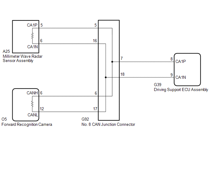
CAUTION / NOTICE / HINT
NOTICE:
- Inspect the fuses for circuits related to this system before performing the following procedure.
- Before measuring the resistance of the CAN bus, turn the power switch
off and leave the vehicle for 1 minute or more without operating the key
or any switches, or opening or closing the doors. After that,
disconnect the cable from the negative (-) auxiliary battery terminal
and leave the vehicle for 1 minute or more before measuring the
resistance.
- After turning the power switch off, waiting time may be required before
disconnecting the cable from the negative (-) auxiliary battery
terminal. Therefore, make sure to read the disconnecting the cable from
the negative (-) auxiliary battery terminal notices before proceeding
with work.
Click here 
- When replacing the driving support ECU assembly, always replace it with a
new one. If a driving support ECU assembly which was installed to
another vehicle is used, the information stored in the driving support
ECU assembly will not match the information from the vehicle. As a
result, a DTC may be stored.
- When replacing the forward recognition camera, always replace it with a
new one. If a forward recognition camera which was installed to another
vehicle is used, the information stored in the forward recognition
camera will not match the information from the vehicle. As a result, a
DTC may be stored.
- If the forward recognition camera has been replaced with a new one, be sure to perform forward recognition camera adjustment.
Click here 
- When replacing the millimeter wave radar sensor assembly, always replace
it with a new one. If a millimeter wave radar sensor assembly which was
installed to another vehicle is used, the information stored in the
millimeter wave radar sensor assembly will not match the information
from the vehicle. As a result, a DTC may be stored.
- When the millimeter wave radar sensor assembly is replaced with a new
one, adjustment of the radar sensor beam axis must be performed.
Click here 
- Confirm that the connectors are securely connected, as a partially connected connector can cause this DTC to be stored.
PROCEDURE
|
1. | READ VALUE USING TECHSTREAM (CAN BUS CHECK) |
(a) Connect the Techstream to the DLC3.
(b) Turn the power switch on (IG).
(c) Turn the Techstream on.
(d) Enter the following menus: System Select / Can Bus Check.
Click here 
CAN Bus Check
|
Result | Proceed to |
|
All of the ECUs and sensors that are currently connected to the CAN communication system are displayed |
A |
| None
of the ECUs and sensors that are currently connected to the CAN
communication system are displayed, or some of them are not displayed |
B |
| B |
 | GO TO CAN COMMUNICATION SYSTEM |
|
A |
 | |
(a) Check for DTCs.
Chassis > Front Recognition Camera > Trouble Codes
|
Result | Proceed to |
|
DTCs are not output | A |
|
Only DTC U0235 is output |
B |
| Only DTC U1104 is output |
C |
| DTC U0235 and U1104 are output |
D |
| B |
 | GO TO STEP 6 |
| C |
 | REPLACE DRIVING SUPPORT ECU ASSEMBLY |
| D |
 | GO TO STEP 7 |
|
A |
 | |
(a) Check for DTCs.
Chassis > ABS/VSC/TRAC > Trouble Codes
|
Result | Proceed to |
|
Electronically controlled brake system DTCs are not output |
A |
| Electronically controlled brake system DTCs are output |
B |
| B |
 | GO TO ELECTRONICALLY CONTROLLED BRAKE SYSTEM |
|
A |
 | |
| 4. |
TEST MODE INSPECTION (ELECTRONICALLY CONTROLLED BRAKE SYSTEM) |
HINT:
When
entering Test Mode (Signal Check), the skid control ECU (brake booster
with master cylinder assembly) communicates with the driving support ECU
assembly to judge whether the vehicle is equipped with the
pre-collision system. Therefore, do not exit Test Mode (Signal Check)
within 5 seconds of entering Test Mode (Signal Check).
(a) Procedure to Enter Test Mode (Signal Check)
(1) Turn the power switch off.
(2) Check that the steering wheel is centered.
(3) Check that the shift lever is in P.
(4) Connect the Techstream to the DLC3.
(5) Turn the power switch on (IG).
(6) Turn the Techstream on.
(7)
Switch the skid control ECU (brake booster with master cylinder
assembly) to Test Mode (Signal Check) using the Techstream. Enter the
following menus: Chassis / ABS/VSC/TRAC / Utility / Signal Check.
HINT:
Do
not exit Test Mode (Signal Check) within 5 seconds of entering Test
Mode (Signal Check). If Test Mode (Signal Check) is exited within 5
seconds of entering Test Mode (Signal Check), DTC U1104 may be stored.
If DTC U1104 is output after exiting Test Mode (Signal Check), enter
Test Mode (Signal Check) again, wait at least 5 seconds, then recheck
for DTCs.
Chassis > ABS/VSC/TRAC > Utility
|
Tester Display |
| Signal Check |
(8)
Check that the ABS warning, brake warning / yellow (minor malfunction)
and slip indicator lights come on for several seconds and then blink in
the Test Mode pattern.
HINT:
If
the ABS warning light, brake warning light / yellow (minor malfunction)
or slip indicator light remains illuminated or does not illuminate when
Test Mode (Signal Check) is entered, a component or wire harness may be
malfunctioning.
(b) End of Test Mode (Signal Check)
(1) End Test Mode (signal check) using the Techstream
- Turn the power switch off and enter normal mode.
- Remove the Techstream.
|
NEXT |
 | |
(a) Clear the DTCs.
Body Electrical > Pre-Collision 2 > Clear DTCs
(b) Make sure that the DTC detection conditions are met.
HINT:
If the detection conditions are not met, the system cannot detect the malfunction.
(c) Check for DTCs.
Body Electrical > Pre-Collision 2 > Trouble Codes
|
Result | Proceed to |
|
DTC U1104 is not output |
A |
| DTC U1104 is output |
B |
| A |
 | END |
| B |
 | REPLACE DRIVING SUPPORT ECU ASSEMBLY |
(a) Turn the power switch off.
(b) Disconnect the cable from the negative (-) auxiliary battery terminal.
| (c) Disconnect the O5 forward recognition camera connector. |
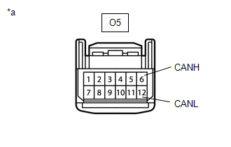 |
|
*a | Front view of wire harness connector
(to Forward Recognition Camera) | | |
(d) Measure the resistance according to the value(s) in the table below.
Standard Resistance:
|
Tester Connection | Condition |
Specified Condition |
|
O5-6 (CANH) - O5-12 (CANL) |
Cable disconnected from negative (-) auxiliary battery terminal |
108 to 132 Ω |
HINT:
If the result is not as specified, a malfunction in a CAN communication line is suspected.
(e) Connect the O5 forward recognition camera connector.
| OK |
 | REPLACE MILLIMETER WAVE RADAR SENSOR ASSEMBLY |
| NG |
 | REPAIR OR REPLACE HARNESS OR CONNECTOR (CAN BUS LINE) |
(a) Turn the power switch off.
(b) Disconnect the cable from the negative (-) auxiliary battery terminal.
| (c) Disconnect the O5 forward recognition camera connector. |
 |
|
*a | Front view of wire harness connector
(to Forward Recognition Camera) | | |
(d) Measure the resistance according to the value(s) in the table below.
Standard Resistance:
|
Tester Connection | Condition |
Specified Condition |
|
O5-6 (CANH) - O5-12 (CANL) |
Cable disconnected from negative (-) auxiliary battery terminal |
108 to 132 Ω |
HINT:
If the result is not as specified, a malfunction in a CAN communication line is suspected.
(e) Connect the O5 forward recognition camera connector.
| OK |
 | REPLACE FORWARD RECOGNITION CAMERA |
| NG |
 | REPAIR OR REPLACE HARNESS OR CONNECTOR (CAN BUS LINE) |
Utility
UTILITY
NOTICE:
CONTROL MODE
HINT:
- This mode is used to check the operation of the pre-collision system
when reproducing situations when the pre-collision system operated
unnecessarily.
- Operating the pre-collision brake assist control or pre-collision
braking control when reproducing problem symptoms may lead to a
dangerous situation. To avoid this, do not attempt to operate the
pre-collision braking control, only operate the pre-collision warning
control (buzzer and warning message) when reproducing the problem
symptoms.
|
PCS Control Operated |
Buzzer Sound |
|
Pre-collision warning control |
Intermittent (Long) |
|
Pre-collision brake assist control |
Intermittent (Short) |
|
Pre-collision braking control |
Continuous |
(a) Connect the Techstream to the DLC3.
(b) Enter the following menus: Body Electrical / Pre-Collision 2 / Utility / Control Mode.
(c) Perform Control Mode according to the display on the Techstream.
Body Electrical > Pre-Collision 2 > Utility
|
Tester Display |
| Control Mode |
FRONT BEAM AXIS ADJUSTMENT
HINT:
Front Beam Axis Adjustment of the millimeter wave radar sensor assembly is performed using the Techstream.
(a) Perform Front Beam Axis Adjustment according to the display on the Techstream.
Click here 
Body Electrical > Pre-Collision 2 > Utility
|
Tester Display |
| Front Beam Axis Adjustment |
FRONT BEAM AXIS MISALIGNMENT READING
HINT:
The amount of misalignment of the millimeter wave radar sensor assembly can be checked using the Techstream.
(a) Perform Front Beam Axis Misalignment Reading according to the display on the Techstream.
Click here 
Body Electrical > Pre-Collision 2 > Utility
|
Tester Display |
| Front Beam Axis Misalignment Reading |
FRONT BEAM AXIS OFFSET READING
HINT:
The offset of the millimeter wave radar sensor assembly can be checked using the Techstream.
(a) Perform Front Beam Axis Offset Reading according to the display on the Techstream.
Click here 
Body Electrical > Pre-Collision 2 > Utility
|
Tester Display |
| Front Beam Axis Offset Reading |
HISTORY CLEAR
HINT:
If the status of any history data is "ON", clear the history data.
(a) Connect the Techstream to the DLC3.
(b) Enter the following menus: Body Electrical / Pre-Collision 2 / Utility / History Clear.
(c) Perform History Clear according to the display on the Techstream.
Body Electrical > Pre-Collision 2 > Utility
|
Tester Display |
| History Clear |
Vehicle Control History
VEHICLE CONTROL HISTORY
VEHICLE CONTROL HISTORY
(a) A part of the control history can be confirmed using the vehicle control history.
Click here 


 Communication Table


