COMPONENTS ILLUSTRATION *1 SPARE WHEEL COVER ASSEMBLY - - ILLUSTRATION *A for Gasoline Model *B for HV Model *1 LUGGAGE COMPARTMENT INNER TRIM PAD *2 REAR CENTER SEAT OUTER BELT ASSEMBLY *3 REAR SEAT CUSHION ASSEMBLY *4 REAR SEAT CUSHION LOCK HOOK *5 REAR SEAT HEADREST ASSEMBLY *6 REAR SEAT INNER WITH CENTER BELT ASSEMBLY RH *7 REAR SEATBACK ASSEMBLY LH *8 REAR SEATBACK ASSEMBLY RH Tightening torque for "Major areas involving basic vehicle performance such as moving/turning/stopping": N*m (kgf*cm, ft.*lbf) ● Non-reusable part INSPECTION PROCEDURE 1. INSPECT REAR SEAT INNER WITH CENTER BELT ASSEMBLY RH (for Gasoline Model) (a) Measure the resistance according to the value(s) in the table below. Standard Resistance: Tester Connection Condition Specified Condition 5 - 4 Rear RH seat belt unfastened Below 1 Ω If the result is not as specified, replace the rear seat inner with center belt assembly RH. *a Component without harness connected (Rear Seat Inner with Center Belt Assembly RH) 2. INSPECT REAR SEAT INNER WITH CENTER BELT ASSEMBLY RH (for HV Model) (a) Measure the resistance according to the value(s) in the table below. Standard Resistance: Tester Connection Condition Specified Condition 4 - 3 Rear RH seat belt unfastened Below 1 Ω If the result is not as specified, replace the rear seat inner with center belt assembly RH. *a Component without harness connected (Rear Seat Inner with Center Belt Assembly RH) INSTALLATION PROCEDURE 1. INSTALL REAR SEAT INNER WITH CENTER BELT ASSEMBLY RH (a) Install the rear seat inner with center belt assembly RH with the bolt. Torque: 42 N·m {428 kgf·cm, 31 ft·lbf} NOTICE: Do
not allow the anchor part of the rear seat inner with center belt
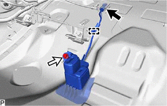
assembly RH to overlap the protruding parts of the vehicle body. Protruding Part (b) Engage the clamp. (c) Connect the connector. 2. INSTALL REAR SEATBACK ASSEMBLY RH Click here 3. INSTALL REAR SEATBACK ASSEMBLY LH Click here 4. INSTALL REAR SEAT CUSHION LOCK HOOK Click here 5. INSTALL REAR SEAT CUSHION ASSEMBLY Click here 6. CONNECT REAR CENTER SEAT OUTER BELT ASSEMBLY Click here 7. INSTALL REAR SEAT HEADREST ASSEMBLY Click here 8. INSTALL LUGGAGE COMPARTMENT INNER TRIM PAD Click here 9. INSTALL SPARE WHEEL COVER ASSEMBLY Click here REMOVAL PROCEDURE 1. REMOVE SPARE WHEEL COVER ASSEMBLY Click here 2. REMOVE LUGGAGE COMPARTMENT INNER TRIM PAD Click here 3. REMOVE REAR SEAT HEADREST ASSEMBLY Click here 4. DISCONNECT REAR CENTER SEAT OUTER BELT ASSEMBLY Click here 5. REMOVE REAR SEAT CUSHION ASSEMBLY Click here 6. REMOVE REAR SEAT CUSHION LOCK HOOK Click here 7. REMOVE REAR SEATBACK ASSEMBLY LH Click here 8. REMOVE REAR SEATBACK ASSEMBLY RH Click here 9. REMOVE REAR SEAT INNER WITH CENTER BELT ASSEMBLY RH (a) Disconnect the connector. (b) Disengage the clamp. (c) Remove the bolt and rear seat inner with center belt assembly RH. HINT: The bolt cannot be removed from the rear seat inner with center belt assembly RH.Components
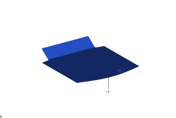
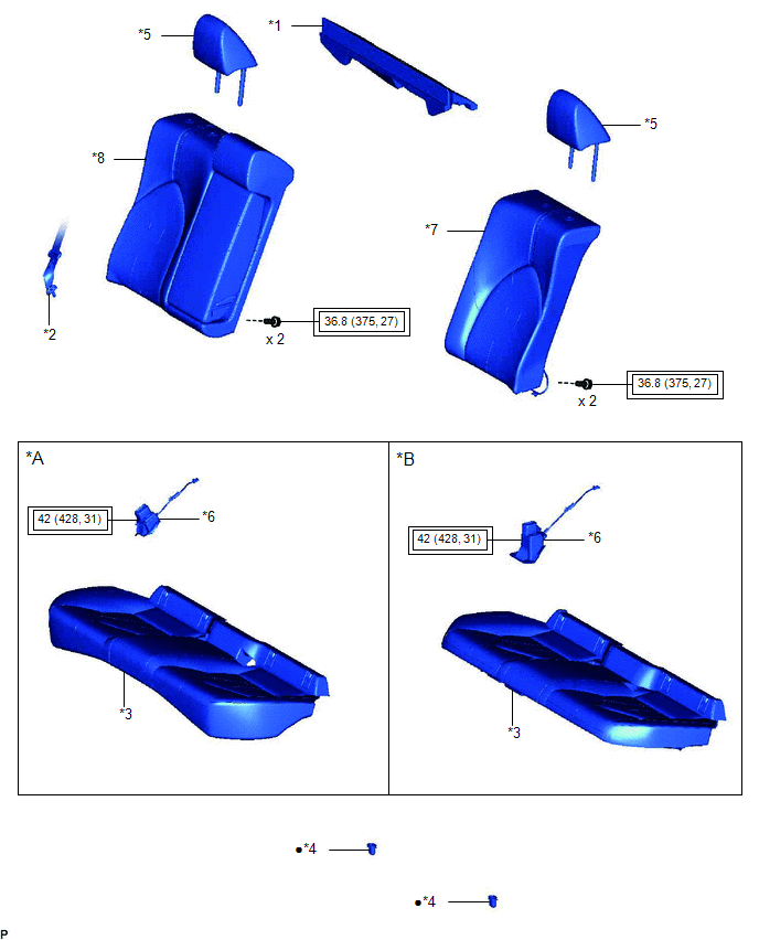

Inspection
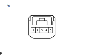
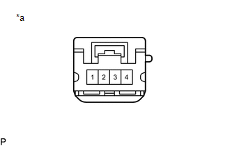
Installation
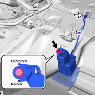


Removal


Toyota Avalon (XX50) 2019-2022 Service & Repair Manual > Brake System (other): Brake Booster(for Gasoline Model)
Components COMPONENTS ILLUSTRATION *1 NO. 1 INSTRUMENT PANEL UNDER COVER SUB-ASSEMBLY - - ILLUSTRATION *1 FRONT CENTER UPPER SUSPENSION BRACE SUB-ASSEMBLY - - Tightening torque for "Major areas involving basic vehicle performance such as moving/turning/stopping" : N*m (kgf*cm, ft.*lbf) N*m (kgf*cm, ...