Installation
INSTALLATION
CAUTION / NOTICE / HINT
CAUTION:
Wear protective gloves. Sharp areas on the seat frame may injure your hands.
PROCEDURE
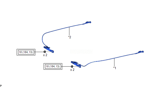
1. INSTALL REAR SEATBACK LOCK ASSEMBLY LH
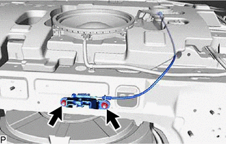
(a) Install the rear seatback lock assembly LH with the 2 nuts.
Torque:
18 N·m {184 kgf·cm, 13 ft·lbf}
(b) Engage the guide to connect the rear seatback lock assembly LH as shown in the illustration.
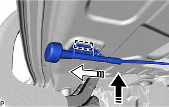
 |
Install in this Direction (1) |
 |
Install in this Direction (2) |
2. INSTALL REAR SEATBACK LOCK ASSEMBLY RH
HINT:
Use the same procedure as for the LH side.
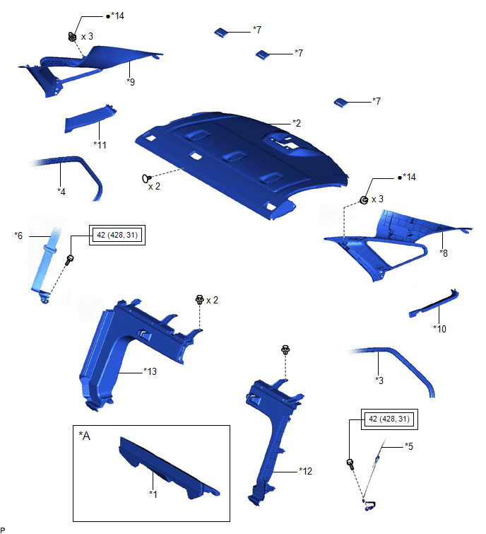
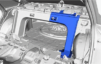
3. INSTALL ROOM PARTITION BOARD RH
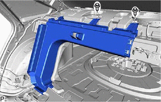
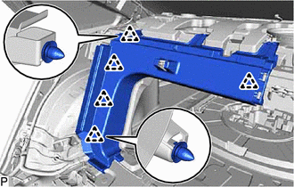
(a) Engage the 5 clips.
(b) Install the room partition board RH with the 2 clips.
4. INSTALL ROOM PARTITION BOARD LH
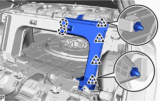
(a) Engage the 4 clips and 2 claws.
(b) Install the room partition board LH with the clip.
5. INSTALL PACKAGE TRAY TRIM PANEL ASSEMBLY
Click here 
6. INSTALL REAR SEAT SHOULDER BELT COVER
Click here 
7. INSTALL ROOF SIDE INNER GARNISH LH
Click here 
8. INSTALL ROOF SIDE INNER GARNISH RH
HINT:
Use the same procedure as for the LH side.
9. INSTALL ROOF SIDE RAIL GARNISH ASSEMBLY LH
Click here 
10. INSTALL ROOF SIDE RAIL GARNISH ASSEMBLY RH
HINT:
Use the same procedure as for the LH side.
11. CONNECT REAR DOOR OPENING TRIM WEATHERSTRIP LH
Click here 
12. CONNECT REAR DOOR OPENING TRIM WEATHERSTRIP RH
Click here 
13. CONNECT REAR SEAT 3 POINT TYPE BELT ASSEMBLY LH
Click here 
14. CONNECT REAR SEAT 3 POINT TYPE BELT ASSEMBLY RH
HINT:
Use the same procedure as for the LH side.
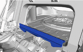
15. INSTALL LUGGAGE COMPARTMENT INNER TRIM PAD (w/o Seat Heater System)
(a) Install the luggage compartment inner trim pad.
16. INSTALL CENTER STOP LIGHT SET
Click here 
17. INSTALL REAR SEAT ASSEMBLY
Click here 
Removal
REMOVAL
CAUTION / NOTICE / HINT
The
necessary procedures (adjustment, calibration, initialization or
registration) that must be performed after parts are removed and
installed, or replaced during rear seatback lock assembly
removal/installation are shown below.
Necessary Procedure After Parts Removed/Installed/Replaced (for Gasoline Model) |
Replaced Part or Performed Procedure |
Necessary Procedure | Effect/Inoperative Function When Necessary Procedures are not Performed |
Link |
|
*: When performing learning using the Techstream.
Click here  |
|
Disconnect cable from negative battery terminal |
Perform steering sensor zero point calibration |
Lane departure alert system (w/ Steering Control) |
 |
|
Pre-collision system |
|
Intelligent clearance sonar system* |
|
Lighting system (for Gasoline Model with Cornering Light) |
|
Memorize steering angle neutral point |
Parking assist monitor system |
 |
|
Panoramic view monitor system |
 |
CAUTION:
- Wear protective gloves. Sharp areas on the parts may injure your hands.
- Some of these service operations affect the SRS airbag system. Read the
precautionary notices concerning the SRS airbag system before servicing.
Click here 
Necessary Procedure After Parts Removed/Installed/Replaced (for HV Model) |
Replaced Part or Performed Procedure |
Necessary Procedure | Effect/Inoperative Function When Necessary Procedures are not Performed |
Link |
|
*: When performing learning using the Techstream.
Click here  |
|
Disconnect cable from negative auxiliary battery terminal |
Perform steering sensor zero point calibration |
Lane departure alert system (w/ Steering Control) |
 |
|
Pre-collision system |
|
Intelligent clearance sonar system* |
|
Lighting system (for HV Model with Cornering Light) |
|
Memorize steering angle neutral point |
Parking assist monitor system |
 |
|
Panoramic view monitor system |
 |
CAUTION:
- Wear protective gloves. Sharp areas on the parts may injure your hands.
- Some of these service operations affect the SRS airbag system. Read the
precautionary notices concerning the SRS airbag system before servicing.
Click here 

PROCEDURE
1. REMOVE REAR SEAT ASSEMBLY
Click here

2. REMOVE CENTER STOP LIGHT SET
Click here

3. REMOVE LUGGAGE COMPARTMENT INNER TRIM PAD (w/o Seat Heater System)
| (a) Remove the luggage compartment inner trim pad. | |
4. DISCONNECT REAR SEAT 3 POINT TYPE BELT ASSEMBLY LH
Click here

5. DISCONNECT REAR SEAT 3 POINT TYPE BELT ASSEMBLY RH
HINT:
Use the same procedure as for the LH side.
6. DISCONNECT REAR DOOR OPENING TRIM WEATHERSTRIP LH
Click here 
7. DISCONNECT REAR DOOR OPENING TRIM WEATHERSTRIP RH
HINT:
Use the same procedure as for the LH side.
8. REMOVE ROOF SIDE RAIL GARNISH ASSEMBLY LH
Click here 
9. REMOVE ROOF SIDE RAIL GARNISH ASSEMBLY RH
HINT:
Use the same procedure as for the LH side.
10. REMOVE ROOF SIDE INNER GARNISH LH
Click here 
11. REMOVE ROOF SIDE INNER GARNISH RH
HINT:
Use the same procedure as for the LH side.
12. REMOVE REAR SEAT SHOULDER BELT COVER
Click here 
13. REMOVE PACKAGE TRAY TRIM PANEL ASSEMBLY
Click here 
14. REMOVE ROOM PARTITION BOARD LH
| (b) Disengage the 2 claws. | |
(c) Disengage the 4 clips to remove the room partition board LH.
15. REMOVE ROOM PARTITION BOARD RH
| (b) Disengage the 5 clips to remove the room partition board RH. |
|
16. REMOVE REAR SEATBACK LOCK ASSEMBLY LH
(a) Release the stopper and disengage the guide as shown in the illustration.
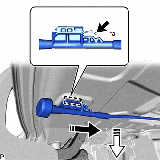
|
*a | Stopper |
 |
Release |
 |
Remove in this Direction (1) |
 |
Remove in this Direction (2) |
| (b) Remove the 2 nuts and rear seatback lock assembly LH. |
|
17. REMOVE REAR SEATBACK LOCK ASSEMBLY RH
HINT:
Use the same procedure as for the LH side.
