Components
COMPONENTS
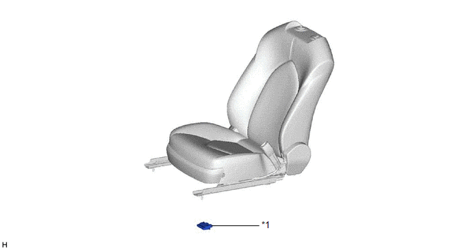
ILLUSTRATION
|
*1 | OCCUPANT DETECTION ECU |
- | - |
Installation
INSTALLATION
PROCEDURE
1. INSTALL OCCUPANT DETECTION ECU
| (a) Engage the claw to install the occupant detection ECU. NOTICE:
If
the occupant detection ECU has been dropped, or there are any cracks,
dents or other defects in the case or connector, replace the occupant
detection ECU with a new one. | |
(b) Connect the 2 connectors.
NOTICE:
When
installing the occupant detection ECU, be careful that the SRS wiring
does not interfere with or is not pinched between other parts.
2. INSTALL FRONT SEAT ASSEMBLY RH
HINT:
Use the same procedure as for the LH side.
Click here

3. PERFORM DIAGNOSTIC SYSTEM CHECK
for Gasoline Model: Click here
for HV Model: Click here
4. PERFORM ZERO POINT CALIBRATION AND SENSITIVITY CHECK
for Gasoline Model: Click here
for HV Model: Click here
On-vehicle Inspection
ON-VEHICLE INSPECTION
CAUTION / NOTICE / HINT
CAUTION:
Be sure to correctly follow the removal and installation procedures for the occupant detection ECU.
PROCEDURE
1. INSPECT OCCUPANT DETECTION ECU (for Vehicle not Involved in Collision)
(a) Perform a diagnostic system check.
for Gasoline Model: Click here

for HV Model: Click here
2. INSPECT OCCUPANT DETECTION ECU (for Vehicle Involved in Collision)
(a) Perform a diagnostic system check.
for Gasoline Model: Click here
for HV Model: Click here
(b) Visually check for defects with the occupant detection ECU.
HINT:
The defects are as follows:
- Cracks in the ECU housing
- Dents in the ECU housing
- Chips in the ECU housing
- Cracks or other damage to the connector
- Damage to the serial number
OK:
No defects are found.
If any defects are found, replace the occupant detection ECU with a new one.
Removal
REMOVAL
CAUTION / NOTICE / HINT
The
necessary procedures (adjustment, calibration, initialization or
registration) that must be performed after parts are removed and
installed, or replaced during occupant detection ECU
removal/installation are shown below.
Necessary Procedures After Parts Removed/Installed/Replaced (for Gasoline Model) |
Replaced Part or Performed Procedure |
Necessary Procedure | Effect/Inoperative Function when Necessary Procedure not Performed |
Link |
|
*: When performing learning using the Techstream.
Click here  |
- Replacement of the occupant detection ECU
- Removal/installation of the front passenger seat
| Zero point calibration (Occupant Classification System) |
- Occupant Classification System
- Passenger airbag ON/OFF indicator
- Airbag System (Front passenger side)
- Seat Belt Warning System (Front passenger)
|
|
|
Disconnect cable from negative auxiliary battery terminal |
Perform steering sensor zero point calibration |
Lane Departure Alert System (w/ Steering Control) |
|
|
Pre-collision System |
|
Intelligent Clearance Sonar System* |
|
Lighting System (for Gasoline Model with Cornering Light) |
|
Memorize steering angle neutral point |
Parking Assist Monitor System |
|
|
Panoramic View Monitor System |
|
Necessary Procedures After Parts Removed/Installed/Replaced (for HV Model) |
Replaced Part or Performed Procedure |
Necessary Procedure | Effect/Inoperative Function when Necessary Procedure not Performed |
Link |
|
*: When performing learning using the Techstream.
Click here |
- Replacement of the occupant detection ECU
- Removal/installation of the front passenger seat
| Zero point calibration (Occupant classification system) |
- Occupant classification system
- Passenger airbag ON/OFF indicator
- Airbag system (Front passenger side)
- Seat belt warning system (Front passenger)
|
|
|
Disconnect cable from negative auxiliary battery terminal |
Perform steering sensor zero point calibration |
Lane Departure Alert System (w/ Steering Control) |
|
|
Pre-collision System |
|
Intelligent Clearance Sonar System* |
|
Lighting System (for HV Model with Cornering Light) |
|
Memorize steering angle neutral point |
Parking Assist Monitor System |
|
|
Panoramic View Monitor System |
|
PROCEDURE
1. REMOVE FRONT SEAT ASSEMBLY RH
HINT:
Use the same procedure as for the LH side.
Click here
2. REMOVE OCCUPANT DETECTION ECU
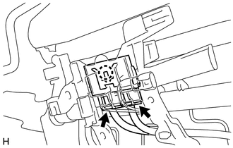
| (a) Disconnect the 2 connectors. | |
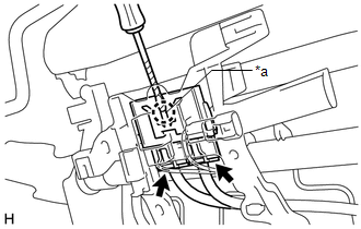
(b) Using a screwdriver with its tip wrapped with protective tape, disengage the claw and remove the occupant detection ECU.