Components
COMPONENTS
ILLUSTRATION
|
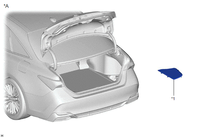
*A | for HV Model |
- | - |
|
*1 | LUGGAGE TRIM SERVICE HOLE COVER |
- | - |
ILLUSTRATION
|
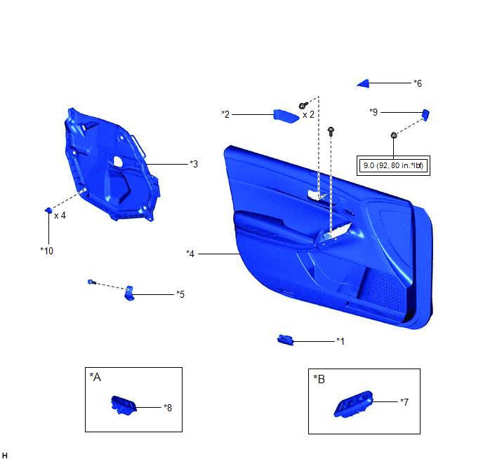
*A | for Front Passenger Side |
*B | for Driver Side |
|
*1 | COURTESY LIGHT ASSEMBLY |
*2 | FRONT DOOR ARMREST COVER SUB-ASSEMBLY |
|
*3 | FRONT DOOR SERVICE HOLE COVER |
*4 | FRONT DOOR TRIM BOARD SUB-ASSEMBLY |
|
*5 | FRONT DOOR TRIM BRACKET |
*6 | FRONT DOOR TRIM POCKET COVER |
|
*7 | MULTIPLEX NETWORK MASTER SWITCH ASSEMBLY WITH FRONT DOOR UPPER ARMREST BASE PANEL |
*8 | POWER WINDOW REGULATOR SWITCH ASSEMBLY WITH FRONT DOOR UPPER ARMREST BASE PANEL |
|
*9 | SIDE AIRBAG PRESSURE SENSOR |
*10 | FRONT DOOR WEATHERSTRIP CLIP |
 |
Tightening torque for "Major areas involving basic vehicle performance such as moving/turning/stopping": N*m (kgf*cm, ft.*lbf) |
- | - |
Installation
INSTALLATION
PROCEDURE
1. INSTALL SIDE AIRBAG PRESSURE SENSOR
(a) Check that the engine switch (for Gasoline Model) or power switch (for HV Model) is off.
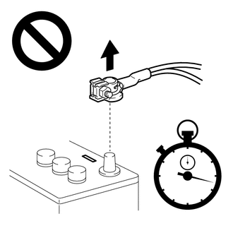
(b) Check that the cable is disconnected from the negative (-) auxiliary battery terminal.
CAUTION:
Wait
at least 90 seconds after disconnecting the cable from the negative (-)
auxiliary battery terminal to disable the SRS system.
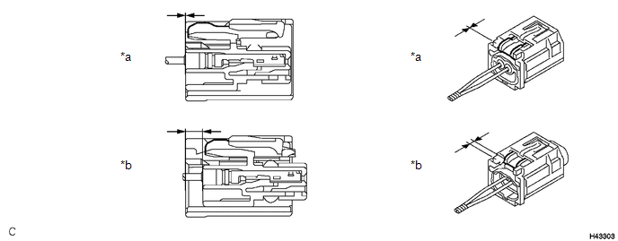
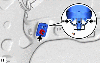
(c) Before connecting the connector, check that the position of the white housing lock is as shown in the illustration.

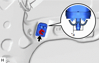
| (d) Engage the 2 stoppers to temporarily install the side airbag pressure sensor to the front door panel. |
|
(e) Install the side airbag pressure sensor with the nut.
Torque:
9.0 N·m {92 kgf·cm, 80 in·lbf}
NOTICE:
- If the side airbag pressure sensor has been dropped, or there are any
cracks, dents or other defects in the case or connector, replace it with
a new one.
- When installing the side airbag pressure sensor, make sure that the wire
harness does not interfere with other parts and is not pinched.
- Make sure that the side airbag pressure sensor stopper is securely engaged to the front door panel.
- Keep the stud bolt and waterproof rubber seal free of foreign matter.
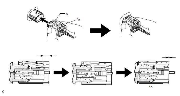
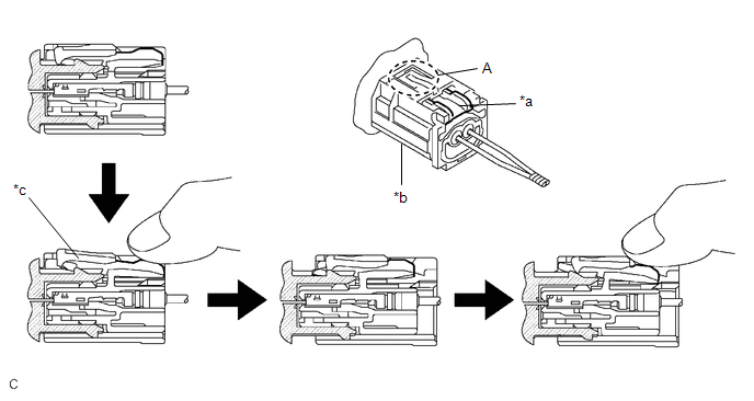
(f) Connect the connector to the side airbag pressure sensor.
|
*a | White Housing Lock | *b |
Connection is completed |
NOTICE:
When connecting any airbag connector, take care not to damage the airbag wire harness.
HINT:
- Be sure to connect the connector until it is locked (when locking, make sure that a click sound can be heard).
- When the connector is locked, the white housing lock will slide. Do not
hold the white housing lock or the part (A) as it may result in an
insecure connection.
(g) Check that there is no looseness in the installed parts of the side airbag pressure sensor.
2. INSTALL FRONT DOOR SERVICE HOLE COVER
Click here

3. INSTALL FRONT DOOR TRIM BRACKET
Click here
4. INSTALL FRONT DOOR TRIM BOARD SUB-ASSEMBLY
Click here
5. INSTALL COURTESY LIGHT ASSEMBLY
Click here
6. INSTALL MULTIPLEX NETWORK MASTER SWITCH ASSEMBLY WITH FRONT DOOR UPPER ARMREST BASE PANEL (for Driver Side)
Click here
7. INSTALL POWER WINDOW REGULATOR SWITCH ASSEMBLY WITH FRONT DOOR UPPER ARMREST BASE PANEL (for Front Passenger Side)
Click here
8. INSTALL FRONT DOOR TRIM POCKET COVER
Click here
9. INSTALL FRONT DOOR ARMREST COVER SUB-ASSEMBLY
Click here
10. CONNECT CABLE TO NEGATIVE AUXILIARY BATTERY TERMINAL
for Gasoline Model: Click here
for HV Model: Click here
NOTICE:
When disconnecting the cable, some systems need to be initialized after the cable is reconnected.
Click here
11. INSTALL LUGGAGE TRIM SERVICE HOLE COVER (for HV Model)
Click here
12. INSPECT POWER WINDOW OPERATION
for Gasoline Model: Click here
for HV Model: Click here
13. PERFORM DIAGNOSTIC SYSTEM CHECK
for Gasoline Model: Click here
for HV Model: Click here
14. INSPECT SRS WARNING LIGHT
for Gasoline Model: Click here
for HV Model: Click here
On-vehicle Inspection
ON-VEHICLE INSPECTION
CAUTION / NOTICE / HINT
CAUTION:
Be sure to correctly follow the removal and installation procedures for the side airbag pressure sensors.
PROCEDURE
1. INSPECT SIDE AIRBAG PRESSURE SENSOR (for Vehicle not Involved in Collision)
(a) Perform a diagnostic system check.
for Gasoline Model: Click here

for HV Model: Click here
2. INSPECT SIDE AIRBAG PRESSURE SENSOR (for Vehicle Involved in Collision and Airbag not Deployed)
(a) Perform a diagnostic system check.
for Gasoline Model: Click here
for HV Model: Click here
(b)
Visually check the side airbag pressure sensors for defects if a front
door of the vehicle or the area around a front door is damaged.
HINT:
The defects are as follows:
- Cracks in the sensor housing
- Dents in the sensor housing
- Chips in the sensor housing
- Cracks or other damage to the connector
- Damage to the waterproof rubber seal
OK:
No defects are found.
If any defects are found, replace the side airbag pressure sensor with a new one.
3. INSPECT SIDE AIRBAG PRESSURE SENSOR (for Vehicle Involved in Collision and Airbag is Deployed)
(a)
When airbags have deployed as the result of a collision, be sure to
replace all side airbag pressure sensors in the damaged areas (anywhere
in need of repair).
(b) Visually check the side airbag pressure sensors in undamaged areas for defects.
HINT:
The defects are as follows:
- Cracks in the sensor housing
- Dents in the sensor housing
- Chips in the sensor housing
- Cracks or other damage to the connector
- Damage to the waterproof rubber seal
OK:
No defects are found.
If
any defects are found or a side airbag pressure sensor has detected a
major collision, replace the side airbag pressure sensor with a new one.
Removal
REMOVAL
CAUTION / NOTICE / HINT
The
necessary procedures (adjustment, calibration, initialization or
registration) that must be performed after parts are removed and
installed, or replaced during side airbag pressure sensor
removal/installation are shown below.
Necessary Procedures After Parts Removed/Installed/Replaced (for Gasoline Model) |
Replaced Part or Performed Procedure |
Necessary Procedure | Effect/Inoperative Function when Necessary Procedure not Performed |
Link |
|
*: When performing learning using the Techstream.
Click here  |
|
Disconnect cable from negative auxiliary battery terminal |
Perform steering sensor zero point calibration |
Lane Departure Alert System (w/ Steering Control) |
|
|
Pre-collision System |
|
Intelligent Clearance Sonar System* |
|
Lighting System (for Gasoline Model with Cornering Light) |
|
Memorize steering angle neutral point |
Parking Assist Monitor System |
|
|
Panoramic View Monitor System |
|
Necessary Procedures After Parts Removed/Installed/Replaced (for HV Model) |
Replaced Part or Performed Procedure |
Necessary Procedure | Effect/Inoperative Function when Necessary Procedure not Performed |
Link |
|
*: When performing learning using the Techstream.
Click here |
|
Disconnect cable from negative auxiliary battery terminal |
Perform steering sensor zero point calibration |
Lane Departure Alert System (w/ Steering Control) |
|
|
Pre-collision System |
|
Intelligent Clearance Sonar System* |
|
Lighting System (for HV Model with Cornering Light) |
|
Memorize steering angle neutral point |
Parking Assist Monitor System |
|
|
Panoramic View Monitor System |
|
PROCEDURE
1. PRECAUTION
CAUTION:
Be sure to read Precaution thoroughly before servicing.
for Gasoline Model: Click here
for HV Model: Click here
NOTICE:
After
turning the engine switch (for Gasoline Model) or power switch (for HV
Model) off, waiting time may be required before disconnecting the cable
from the negative (-) auxiliary battery terminal. Therefore, make sure
to read the disconnecting the cable from the negative (-) auxiliary
battery terminal notices before proceeding with work.
Click here
2. REMOVE LUGGAGE TRIM SERVICE HOLE COVER (for HV Model)
Click here
3. DISCONNECT CABLE FROM NEGATIVE AUXILIARY BATTERY TERMINAL
for Gasoline Model: Click here
for HV Model: Click here
CAUTION:
Wait
at least 90 seconds after disconnecting the cable from the negative (-)
auxiliary battery terminal to disable the SRS system.

NOTICE:
When disconnecting the cable, some systems need to be initialized after the cable is reconnected.
Click here
4. REMOVE FRONT DOOR ARMREST COVER SUB-ASSEMBLY
Click here
5. REMOVE FRONT DOOR TRIM POCKET COVER
Click here
6. REMOVE MULTIPLEX NETWORK MASTER SWITCH ASSEMBLY WITH FRONT DOOR UPPER ARMREST BASE PANEL (for Driver Side)
Click here
7. REMOVE POWER WINDOW REGULATOR SWITCH ASSEMBLY WITH FRONT DOOR UPPER ARMREST BASE PANEL (for Front Passenger Side)
Click here
8. REMOVE COURTESY LIGHT ASSEMBLY
Click here
9. REMOVE FRONT DOOR TRIM BOARD SUB-ASSEMBLY
Click here
10. REMOVE FRONT DOOR TRIM BRACKET
Click here
11. REMOVE FRONT DOOR SERVICE HOLE COVER
Click here
12. REMOVE SIDE AIRBAG PRESSURE SENSOR
(a) Check that the engine switch (for Gasoline Model) or power switch (for HV Model) is off.
(b) Check that the cable is disconnected from the negative (-) auxiliary battery terminal.
CAUTION:
Wait
at least 90 seconds after disconnecting the cable from the negative (-)
auxiliary battery terminal to disable the SRS system.
(c) Disconnect the connector from the side airbag pressure sensor.
NOTICE:
When disconnecting any airbag connector, take care not to damage the airbag wire harness.
(1) Push down the white housing lock and slide the yellow CPA. (At this time, the connector cannot be disconnected yet.)
|
*a | White Housing Lock | *b |
Yellow CPA |
| *c |
Connector lock is released | - |
- |
(2) Push down the white housing lock again and disconnect the connector.
NOTICE:
Do not push down the part (A) shown in the illustration when disconnecting the connector.
(d) Remove the nut.
|
*a | Stopper |
 |
Disengage in this Direction |
(e) Disengage the 2 stoppers as shown in the illustration and remove the side airbag pressure sensor.
NOTICE:
Do not drop the side airbag pressure sensor.
(f) Check that the position of the white housing lock is as shown in the illustration.