Installation
INSTALLATION
PROCEDURE
1. INSPECT SPIRAL CABLE SUB-ASSEMBLY
NOTICE:
If
the steering sensor is installed to a misaligned spiral cable
sub-assembly, spiral cable with sensor sub-assembly malfunction DTCs,
such as DTC B1801, C1231 and C1433, will be stored and it will be
impossible to clear them. If this happens, replace the spiral cable
sub-assembly and steering sensor with a new one.
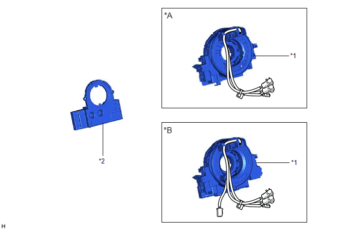
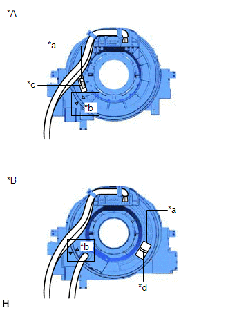
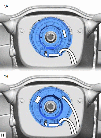
| (a) Check if the spiral cable sub-assembly is centered. OK:
- The connector is positioned at the top.
- The alignment marks are aligned correctly.
- The colored roller or flat cable can be seen in the inspection window.
|
 |
|
*A | w/o Heated Steering Wheel System | |
*B | w/ Heated Steering Wheel System | |
*a | Inspection Window | |
*b | Alignment Mark | |
*c | Colored Roller | |
*d | Flat Cable | | |
(b) If the spiral cable sub-assembly is not centered, center it.
NOTICE:
Make sure to observe the following precautions, otherwise the spiral cable sub-assembly may be damaged.
- Release the interlock before rotating the spiral cable sub-assembly.
- Do not rotate the spiral cable sub-assembly using the airbag wire harness.
- Do not rotate the spiral cable sub-assembly with excessive force.
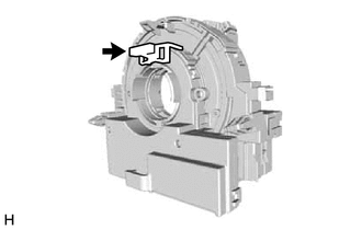
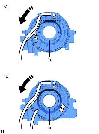
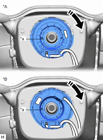
(1) While pushing on the interlock
shown in the illustration, rotate the spiral cable sub-assembly
counterclockwise slowly by hand until it stops.
|
*A | w/o Heated Steering Wheel System |
|
*B | w/ Heated Steering Wheel System |
|
*a | Interlock |
 |
Rotation Direction |
NOTICE:
If
the spiral cable sub-assembly is rotated clockwise in this step, it may
be damaged and may no longer be able to be centered. Make sure to only
rotate the spiral cable sub-assembly counterclockwise.
HINT:
If
the interlock is engaged, the spiral cable sub-assembly will lock when
the connector is near at the top or bottom of the rotation of the spiral
cable sub-assembly.
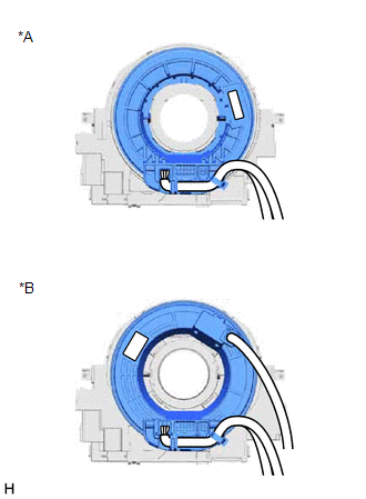
| (2)
If the connector is not positioned at the bottom of the rotation of the
spiral cable sub-assembly when the spiral cable sub-assembly is turned
until it stops, turn the spiral cable sub-assembly clockwise until the
connector is positioned at the bottom as shown in the illustration. |
 |
|
*A | w/o Heated Steering Wheel System | |
*B | w/ Heated Steering Wheel System | | |
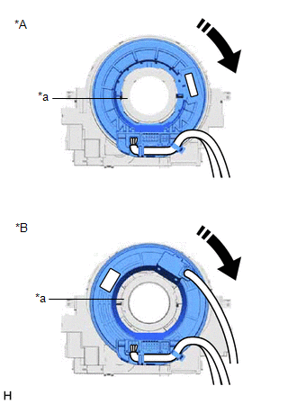
(3)
While pushing on the interlock shown in the illustration, rotate the
spiral cable sub-assembly clockwise approximately 2.5 times.
|
*A | w/o Heated Steering Wheel System |
|
*B | w/ Heated Steering Wheel System |
|
*a | Interlock |
|
|
Rotation Direction |
NOTICE:
If
the spiral cable sub-assembly is rotated clockwise 5 times or more from
the point at which it stops and the connector is positioned at the
bottom, the spiral cable sub-assembly may be damaged.
HINT:
If
the interlock is engaged, the spiral cable sub-assembly will lock when
the connector is near at the top or bottom of the rotation of the spiral
cable sub-assembly.
| (4) Check that the spiral cable sub-assembly is centered. OK:
- The connector is positioned at the top.
- The alignment marks are aligned correctly.
- The colored roller or flat cable can be seen in the inspection window.
| |
|
|
*A | w/o Heated Steering Wheel System | |
*B | w/ Heated Steering Wheel System | |
*a | Inspection Window | |
*b | Alignment Mark | |
*c | Colored Roller | |
*d | Flat Cable | | |
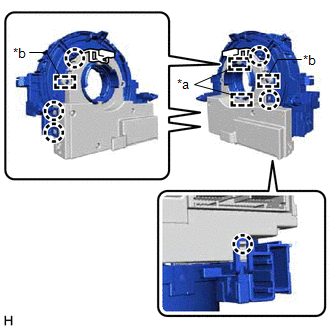
2. INSTALL SPIRAL CABLE SUB-ASSEMBLY
| (a) Align the 2 pins and 2 guides, and engage the 6 claws to install the spiral cable sub-assembly to the steering sensor.
NOTICE:
- Do not remove the lock pin before the spiral cable sub-assembly is installed to the steering sensor.
- Do not damage the pins of the spiral cable sub-assembly or guides of the steering sensor.
- The spiral cable sub-assembly can be rotated up to 30° even when the
interlock is engaged. Therefore, make sure that both guides are aligned
properly when installing the spiral cable sub-assembly to the steering
sensor.
|
 |
|
*a | Guide | |
*b | Pin | |
*c | Lock Pin | | |
| (b) Remove the lock pin from the steering sensor. | |
3. INSTALL SPIRAL CABLE WITH SENSOR SUB-ASSEMBLY
NOTICE:
- Do not remove/install the spiral cable with sensor sub-assembly with the
auxiliary battery connected and the engine switch (for Gasoline Model)
or power switch (for HV Model) on (IG).
- Do not rotate the spiral cable with sensor sub-assembly without the
steering wheel assembly installed, with the auxiliary battery connected
and the engine switch (for Gasoline Model) or power switch (for HV
Model) on (IG).
- Ensure that the steering wheel assembly is installed and aligned straight when inspecting the steering sensor.
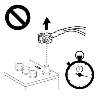
(a) Check that the engine switch (for Gasoline Model) or power switch (for HV Model) is off.
(b) Check that the cable is disconnected from the negative (-) auxiliary battery terminal.
CAUTION:
Wait
at least 90 seconds after disconnecting the cable from the negative (-)
auxiliary battery terminal to disable the SRS system.
(c) Check that the front wheels are aligned facing straight ahead.
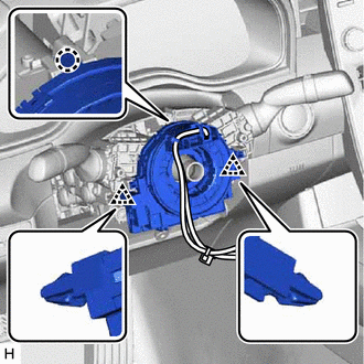
(d) Engage the claw and 2 clips to install the spiral cable with sensor sub-assembly.
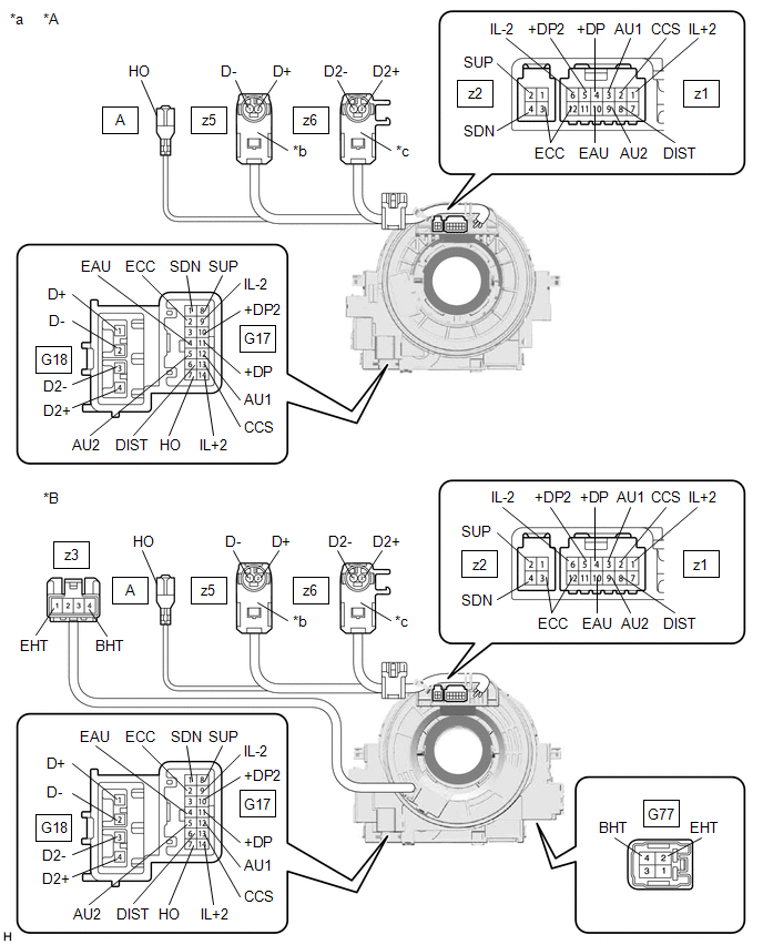
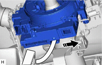
(e) Install the wire harness to the spiral cable with sensor sub-assembly as shown in the illustration.

|
|
Install in this Direction |
(f) Connect each connector.
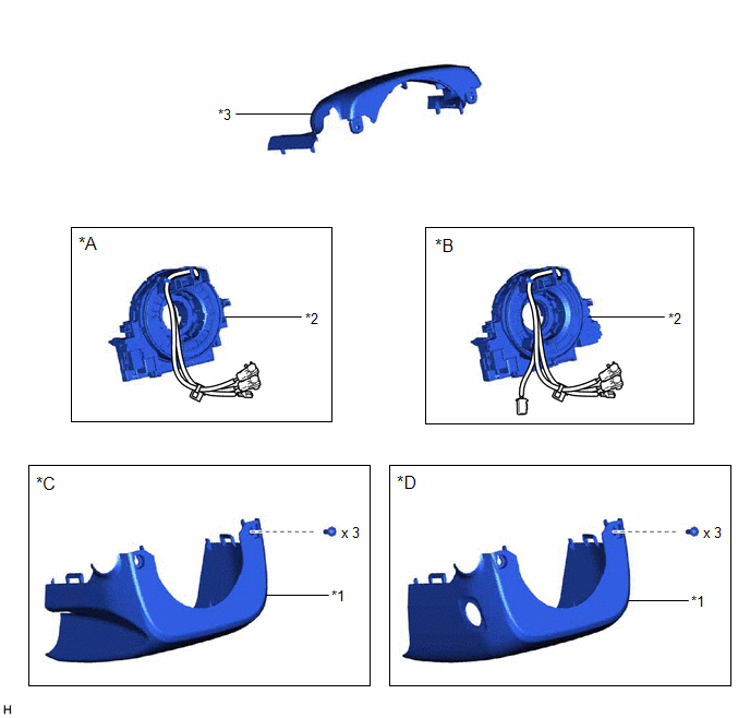
4. INSTALL UPPER STEERING COLUMN COVER (for Manual Tilt and Manual Telescopic Steering Column)
Click here 
5. INSTALL UPPER STEERING COLUMN COVER (for Power Tilt and Power Telescopic Steering Column)
Click here
6. INSTALL LOWER STEERING COLUMN COVER (for Manual Tilt and Manual Telescopic Steering Column)
Click here
7. INSTALL LOWER STEERING COLUMN COVER (for Power Tilt and Power Telescopic Steering Column)
Click here
8. ALIGN FRONT WHEELS FACING STRAIGHT AHEAD
9. INSPECT AND ADJUST SPIRAL CABLE WITH SENSOR SUB-ASSEMBLY
(a) Check that the engine switch (for Gasoline Model) or power switch (for HV Model) is off.
(b) Check that the cable is disconnected from the negative (-) auxiliary battery terminal.
CAUTION:
Wait
at least 90 seconds after disconnecting the cable from the negative (-)
auxiliary battery terminal to disable the SRS system.
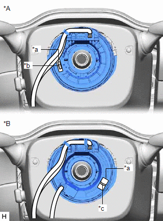
| (c) Check if the spiral cable with sensor sub-assembly is centered. OK:
- The connector is positioned at the top.
- The colored roller or flat cable can be seen in the inspection window.
|
 |
|
*A | w/o Heated Steering Wheel System | |
*B | w/ Heated Steering Wheel System | |
*a | Inspection Window | |
*b | Colored Roller | |
*c | Flat Cable | | |
(d) If the spiral cable with sensor sub-assembly is not centered, center it.
NOTICE:
Make sure to observe the following precautions, otherwise the spiral cable with sensor sub-assembly may be damaged.
- Do not rotate the spiral cable with sensor sub-assembly with the
auxiliary battery connected and the engine switch (for Gasoline Model)
or power switch (for HV Model) on (IG).
- Release the interlock before rotating the spiral cable with sensor sub-assembly.
- Do not rotate the spiral cable with sensor sub-assembly using the airbag wire harness.
- Do not rotate the spiral cable with sensor sub-assembly with excessive force.
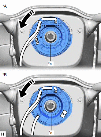
(1) While pushing on the interlock
shown in the illustration, rotate the spiral cable with sensor
sub-assembly counterclockwise slowly by hand until it stops.
|
*A | w/o Heated Steering Wheel System |
|
*B | w/ Heated Steering Wheel System |
|
*a | Interlock |
|
|
Rotation Direction |
NOTICE:
If
the spiral cable with sensor sub-assembly is rotated clockwise in this
step, it may be damaged and may no longer be able to be centered. Make
sure to only rotate the spiral cable with sensor sub-assembly
counterclockwise.
HINT:
If
the interlock is engaged, the spiral cable with sensor sub-assembly will
lock when the connector is near at the top or bottom of the rotation of
the spiral cable with sensor sub-assembly.
| (2)
If the connector is not positioned at the bottom of the rotation of the
spiral cable with sensor sub-assembly when the spiral cable with sensor
sub-assembly is turned until it stops, turn the spiral cable with
sensor sub-assembly clockwise until the connector is positioned at the
bottom as shown in the illustration. |
 |
|
*A | w/o Heated Steering Wheel System | |
*B | w/ Heated Steering Wheel System | | |
(3)
While pushing on the interlock shown in the illustration, rotate the
spiral cable with sensor sub-assembly clockwise approximately 2.5 times.
|
*A | w/o Heated Steering Wheel System |
|
*B | w/ Heated Steering Wheel System |
|
*a | Interlock |
|
|
Rotation Direction |
NOTICE:
If
the spiral cable with sensor sub-assembly is rotated clockwise 5 times
or more from the point at which it stops and the connector is positioned
at the bottom, the spiral cable with sensor sub-assembly may be
damaged.
HINT:
If the
interlock is engaged, the spiral cable with sensor sub-assembly will
lock when the connector is near at the top or bottom of the rotation of
the spiral cable with sensor sub-assembly.
| (4) Check that the spiral cable with sensor sub-assembly is centered. OK:
- The connector is positioned at the top.
- The colored roller or flat cable can be seen in the inspection window.
NOTICE: If the
spiral cable with sensor sub-assembly cannot be centered, it may be
damaged. Replace the spiral cable sub-assembly and steering sensor with a
new one. | |
|
|
*A | w/o Heated Steering Wheel System | |
*B | w/ Heated Steering Wheel System | |
*a | Inspection Window | |
*b | Colored Roller | |
*c | Flat Cable | | |
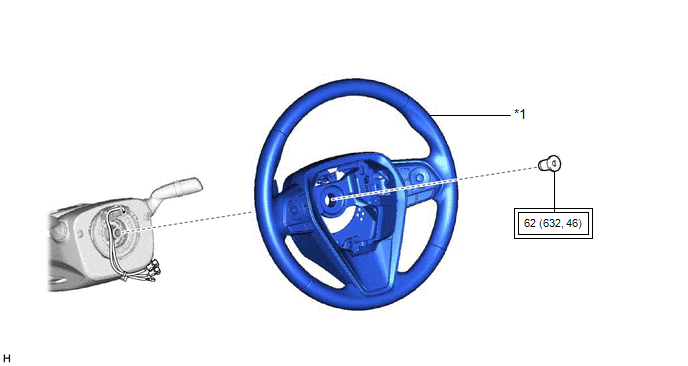
10. INSTALL STEERING WHEEL ASSEMBLY
Click here
11. CHECK STEERING WHEEL CENTER POINT
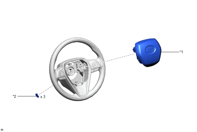
12. INSTALL HORN BUTTON ASSEMBLY
Click here
13. INSTALL LOWER NO. 2 STEERING WHEEL COVER
Click here
14. CONNECT CABLE TO NEGATIVE AUXILIARY BATTERY TERMINAL
for Gasoline Model: Click here
for HV Model: Click here
NOTICE:
When disconnecting the cable, some systems need to be initialized after the cable is reconnected.
Click here
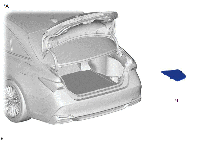
15. INSTALL LUGGAGE TRIM SERVICE HOLE COVER (for HV Model)
Click here
16. INSPECT HORN BUTTON ASSEMBLY
(a) Make sure that the horn sounds.
If the horn does not sound, inspect the horn system.
Click here
17. PERFORM DIAGNOSTIC SYSTEM CHECK
for Gasoline Model: Click here
for HV Model: Click here
18. INSPECT SRS WARNING LIGHT
for Gasoline Model: Click here
for HV Model: Click here
19. CUSTOMIZE POWER TILT AND POWER TELESCOPIC STEERING COLUMN SYSTEM (for Power Tilt and Power Telescopic Steering Column)
Click here
20. PERFORM INITIALIZATION AND CALIBRATION (for Gasoline Model)
for Parking Assist Monitor System Initialization: Click here
for Parking Assist Monitor System Calibration: Click here
for Panoramic View Monitor System Initialization: Click here
for Panoramic View Monitor System Calibration: Click here
for Intelligent Clearance Sonar System Calibration: Click here
21. PERFORM INITIALIZATION AND CALIBRATION (for HV Model)
for Parking Assist Monitor System Initialization: Click here
for Parking Assist Monitor System Calibration: Click here
for Panoramic View Monitor System Initialization: Click here
for Panoramic View Monitor System Calibration: Click here
for Intelligent Clearance Sonar System Calibration: Click here
Removal
REMOVAL
CAUTION / NOTICE / HINT
The
necessary procedures (adjustment, calibration, initialization or
registration) that must be performed after parts are removed and
installed, or replaced during spiral cable sub-assembly
removal/installation are shown below.
Necessary Procedures After Parts Removed/Installed/Replaced (for Gasoline Model) |
Replaced Part or Performed Procedure |
Necessary Procedure | Effect/Inoperative Function when Necessary Procedure not Performed |
Link |
|
*: When performing learning using the Techstream.
Click here  |
|
Removal/installation of the spiral cable with sensor sub-assembly |
Steering angle zero point learning (Initialize intelligent clearance sonar system) |
- Intelligent Clearance Sonar System
- Intuitive Parking Assist System
|
|
- Steering angle zero point learning (Initialize parking assist monitor system)
- Steering angle setting
| Parking Assist Monitor System |
for Initialization
for Calibration |
|
Steering angle zero point learning (Initialize panoramic view monitor system) |
Panoramic View Monitor System |
for Initialization
for Calibration |
|
Disconnect cable from negative auxiliary battery terminal |
Perform steering sensor zero point calibration |
Lane Departure Alert System (w/ Steering Control) |
|
|
Pre-collision System |
|
Intelligent Clearance Sonar System* |
|
Lighting System (for Gasoline Model with Cornering Light) |
|
Memorize steering angle neutral point |
Parking Assist Monitor System |
|
|
Panoramic View Monitor System |
|
Necessary Procedures After Parts Removed/Installed/Replaced (for HV Model) |
Replaced Part or Performed Procedure |
Necessary Procedure | Effect/Inoperative Function when Necessary Procedure not Performed |
Link |
|
*: When performing learning using the Techstream.
Click here |
|
Removal/installation of the spiral cable with sensor sub-assembly |
Steering angle zero point learning (Initialize intelligent clearance sonar system) |
- Intelligent Clearance Sonar System
- Intuitive Parking Assist System
|
|
- Steering angle zero point learning (Initialize parking assist monitor system)
- Steering angle setting
| Parking Assist Monitor System |
for Initialization
for Calibration |
|
Steering angle zero point learning (Initialize panoramic view monitor system) |
Panoramic View Monitor System |
for Initialization
for Calibration |
|
Disconnect cable from negative auxiliary battery terminal |
Perform steering sensor zero point calibration |
Lane Departure Alert System (w/ Steering Control) |
|
|
Pre-collision System |
|
Intelligent Clearance Sonar System* |
|
Lighting System (for HV Model with Cornering Light) |
|
Memorize steering angle neutral point |
Parking Assist Monitor System |
|
|
Panoramic View Monitor System |
|
PROCEDURE
1. PRECAUTION
CAUTION:
Be sure to read Precaution thoroughly before servicing.
for Gasoline Model: Click here
for HV Model: Click here
NOTICE:
After
turning the engine switch (for Gasoline Model) or power switch (for HV
Model) off, waiting time may be required before disconnecting the cable
from the negative (-) auxiliary battery terminal. Therefore, make sure
to read the disconnecting the cable from the negative (-) auxiliary
battery terminal notices before proceeding with work.
Click here
2. CHANGE POWER TILT AND POWER TELESCOPIC STEERING COLUMN SYSTEM SETTINGS (for Power Tilt and Power Telescopic Steering Column)
Click here
3. ALIGN FRONT WHEELS FACING STRAIGHT AHEAD
4. REMOVE LUGGAGE TRIM SERVICE HOLE COVER (for HV Model)
Click here
5. DISCONNECT CABLE FROM NEGATIVE AUXILIARY BATTERY TERMINAL
for Gasoline Model: Click here
for HV Model: Click here
CAUTION:
Wait
at least 90 seconds after disconnecting the cable from the negative (-)
auxiliary battery terminal to disable the SRS system.

NOTICE:
When disconnecting the cable, some systems need to be initialized after the cable is reconnected.
Click here
6. REMOVE LOWER NO. 2 STEERING WHEEL COVER
Click here
7. REMOVE HORN BUTTON ASSEMBLY
Click here
8. REMOVE STEERING WHEEL ASSEMBLY
Click here
9. REMOVE LOWER STEERING COLUMN COVER (for Manual Tilt and Manual Telescopic Steering Column)
Click here
10. REMOVE LOWER STEERING COLUMN COVER (for Power Tilt and Power Telescopic Steering Column)
Click here
11. REMOVE UPPER STEERING COLUMN COVER (for Manual Tilt and Manual Telescopic Steering Column)
Click here
12. REMOVE UPPER STEERING COLUMN COVER (for Power Tilt and Power Telescopic Steering Column)
Click here
13. REMOVE SPIRAL CABLE WITH SENSOR SUB-ASSEMBLY
NOTICE:
- Do not remove/install the spiral cable with sensor sub-assembly with the
auxiliary battery connected and the engine switch (for Gasoline Model)
or power switch (for HV Model) on (IG).
- Do not rotate the spiral cable with sensor sub-assembly without the
steering wheel assembly installed, with the auxiliary battery connected
and the engine switch (for Gasoline Model) or power switch (for HV
Model) on (IG).
- Ensure that the steering wheel assembly is installed and aligned straight when inspecting the steering sensor.
(a) Check that the engine switch (for Gasoline Model) or power switch (for HV Model) is off.
(b) Check that the cable is disconnected from the negative (-) auxiliary battery terminal.
CAUTION:
Wait
at least 90 seconds after disconnecting the cable from the negative (-)
auxiliary battery terminal to disable the SRS system.
(c) Check that the front wheels are aligned facing straight ahead.
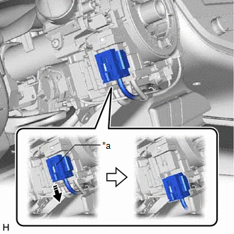
(d)
Slide the slider to release the lock, and then disconnect the yellow
airbag connector from the spiral cable with sensor sub-assembly.
|
*a | Slider |
 |
Release in this Direction |
NOTICE:
When disconnecting any airbag connector, take care not to damage the airbag wire harness.
(e) Disconnect the other connectors from the spiral cable with sensor sub-assembly.
(f) Separate the wire harness from the spiral cable with sensor sub-assembly as shown in the illustration.
|
|
Separate in this Direction |
| (g) Disengage the claw and 2 clips to remove the spiral cable with sensor sub-assembly. |
|
14. REMOVE SPIRAL CABLE SUB-ASSEMBLY
NOTICE:
- Remove the steering sensor from the spiral cable sub-assembly only when
replacing the spiral cable sub-assembly or the steering sensor.
- Removing the steering sensor from the spiral cable sub-assembly without
using a lock pin may result in the center position of the steering
sensor becoming misaligned. Therefore, make sure to use the lock pin
provided with a new spiral cable sub-assembly when removing the steering
sensor from the spiral cable sub-assembly.
- When replacing the steering sensor:
Click here
| (a) Install the lock pin to the steering sensor.
NOTICE:
- Use the lock pin provided with a new spiral cable sub-assembly.
- Do not remove the lock pin before installing the steering sensor to the spiral cable sub-assembly.
| |
| (b) Disengage the 6 claws and 2 pins to remove the spiral cable sub-assembly from the steering sensor.
NOTICE: Do not damage the pins of the spiral cable sub-assembly or guides of the steering sensor. |
|