Components
COMPONENTS
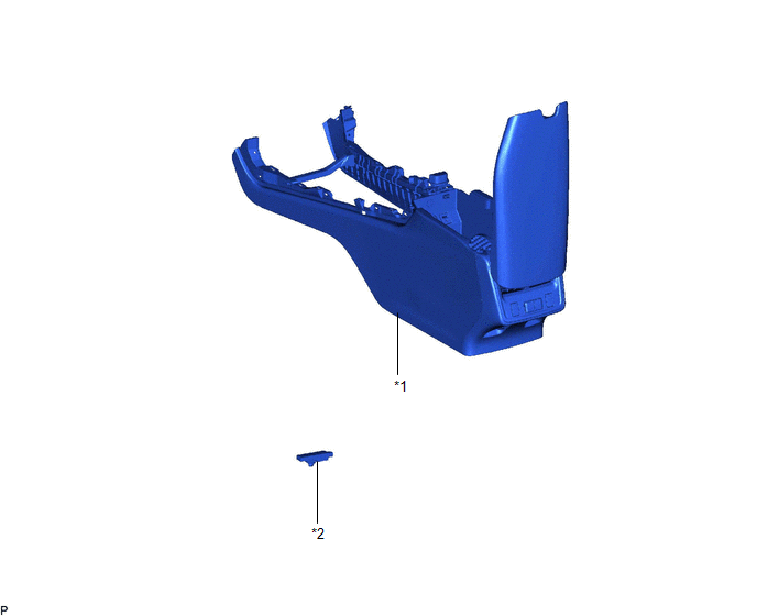
ILLUSTRATION
|
*1 | CONSOLE ASSEMBLY |
*2 | NO. 1 INDOOR ELECTRICAL KEY ANTENNA ASSEMBLY |
Installation
INSTALLATION
PROCEDURE
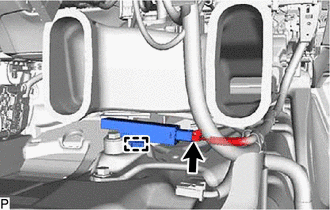
1. INSTALL NO. 1 INDOOR ELECTRICAL KEY ANTENNA ASSEMBLY
(a) Engage the clamp to install the No. 1 indoor electrical key antenna assembly.
NOTICE:
Be careful when installing the No. 1 indoor electrical key antenna assembly. If the No. 1 indoor electrical key antenna assembly is dropped, replace it with a new one.
(b) Connect the connector.
(c) Connect the front floor carpet assembly.
2. INSTALL CONSOLE ASSEMBLY
Click here 
Removal
REMOVAL
PROCEDURE
1. REMOVE CONSOLE ASSEMBLY
Click here 
2. REMOVE NO. 1 INDOOR ELECTRICAL KEY ANTENNA ASSEMBLY
(a) Disconnect the front floor carpet assembly.
| (b) Disconnect the connector. |
|
(c) Disengage the clamp to remove the No. 1 indoor electrical key antenna assembly.
NOTICE:
Be careful when removing the No. 1 indoor electrical key antenna assembly. If the No. 1 indoor electrical key antenna assembly is dropped, replace it with a new one.
Toyota Avalon (XX50) 2019-2022 Owners Manual > Driving: Driving tips
Winter driving tips Carry out the necessary preparations and inspections before driving the vehicle in winter. Always drive the vehicle in a manner appropriate to the prevailing weather conditions. Preparation for winter Use fluids that are appropriate to the prevailing outside temperatures. Engine ...