Power Source Mode does not Change to ON (IG)
DESCRIPTION
If the engine
switch is pressed with the electrical key transmitter sub-assembly in
the cabin, the certification ECU (smart key ECU assembly) receives a
signal and changes the power source mode.
Related Data List and Active Test Items |
Problem Symptom | Data List and Active Test |
|
Power source mode does not change to on (IG) but does change to on (ACC) | Power Source Control
- Power Supply Condition
- IG Relay Monitor (Inside)
- IG Relay Monitor (Outside)
- IG Circuit
Starting Control
|
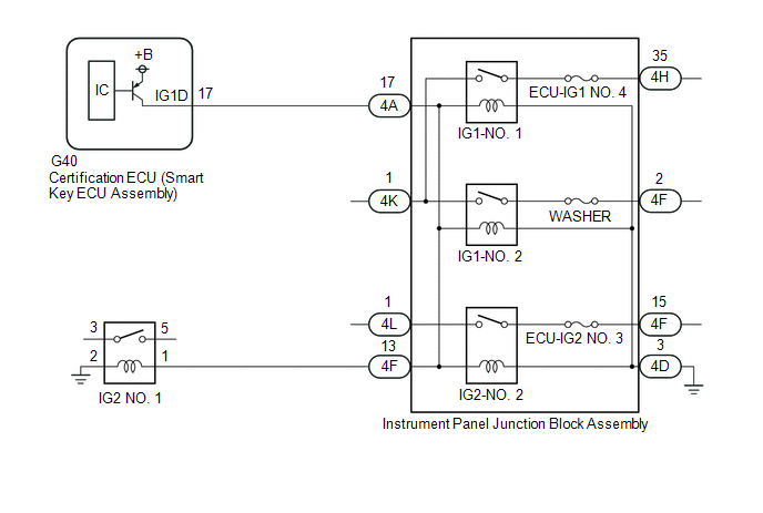
WIRING DIAGRAM
CAUTION / NOTICE / HINT
NOTICE:
- When using the Techstream with the engine switch off, connect the
Techstream to the DLC3 and turn a courtesy light switch on and off at
intervals of 1.5 seconds or less until communication between the
Techstream and the vehicle begins. Then select the vehicle type under
manual mode and enter the following menus: Body Electrical / Smart Key.
While using the Techstream, periodically turn a courtesy light switch on
and off at intervals of 1.5 seconds or less to maintain communication
between the Techstream and the vehicle.
- The smart key system (for Start Function, Gasoline Model) uses the LIN
communication system and CAN communication system. Inspect the
communication function by following How to Proceed with Troubleshooting.
Troubleshoot the smart key system (for Start Function, Gasoline Model)
after confirming that the communication systems are functioning
properly.
Click here 
- Make sure that no DTCs are output. If any DTCs are output, proceed to Diagnostic Trouble Code Chart.
- If the smart key system (for Start Function, Gasoline Model) has been
disabled, enable the system before performing troubleshooting.
Click here
- Inspect the fuses of circuits related to this system before performing the following procedure.
- Before replacing the certification ECU (smart key ECU assembly), refer to Registration.
Click here
- After completing repairs, confirm that the problem does not recur.
- After performing repairs, confirm that no DTCs are output by performing "DTC Output Confirmation Operation."
PROCEDURE
(a) Using the Techstream, check for certification ECU (smart key ECU assembly) DTCs.
Body Electrical > Power Source Control > Trouble Codes Body
Electrical > Smart Key > Trouble Codes Body Electrical >
Starting Control > Trouble Codes |
Result | Proceed to |
|
DTCs are not output | A |
|
Smart key system (for Start Function, Gasoline Model) DTCs are output |
B |
| B |
 | GO TO DIAGNOSTIC TROUBLE CODE CHART |
|
A |
 | |
| 2. |
CHECK CERTIFICATION ECU (SMART KEY ECU ASSEMBLY) |
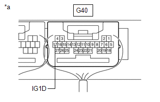
| (a) Measure the voltage according to the value(s) in the table below.
Standard Voltage: |
Tester Connection | Condition |
Specified Condition | |
G40-17 (IG1D) - Body ground |
Engine switch off → Engine switch on (ACC) |
1 V or less → 9 V or higher | |
 |
|
*a | Component with harness connected (Certification ECU (Smart Key ECU Assembly)) | | |
| NG |
| REPLACE CERTIFICATION ECU (SMART KEY ECU ASSEMBLY) |
|
OK | |
| |
| 3. |
CHECK HARNESS AND CONNECTOR (CERTIFICATION ECU (SMART KEY ECU ASSEMBLY) - INSTRUMENT PANEL JUNCTION BLOCK ASSEMBLY) |
(a) Disconnect the 4A, 4D, 4L and 4K instrument panel junction block assembly connectors.
(b) Measure the resistance according to the value(s) in the table below.
Standard Resistance:
|
Tester Connection | Condition |
Specified Condition |
|
G40-17 (IG1D) - 4A-17 |
Always | Below 1 Ω |
|
4D-3 - Body ground | Always |
Below 1 Ω |
|
G40-17 (IG1D) or 4A-17 - Other terminals and body ground |
Always | 10 kΩ or higher |
(c) Measure the voltage according to the value(s) in the table below.
Standard Voltage:
|
Tester Connection | Condition |
Specified Condition |
|
4K-1 - Body ground | Always |
11 to 14 V |
|
4L-1 - Body ground | Always |
11 to 14 V |
| NG |
| REPAIR OR REPLACE HARNESS OR CONNECTOR |
|
OK | |
| |
| 4. |
CHECK INSTRUMENT PANEL JUNCTION BLOCK ASSEMBLY (IG1-NO. 1, IG1-NO. 2, IG2-NO. 2 RELAY) |
(a) Remove the instrument panel junction block assembly.
Click here
(b) Connect all of the instrument panel junction block assembly connectors.
(c) Connect the G40 certification ECU (smart key ECU assembly) connector.
(d) Measure the voltage according to the value(s) in the table below.
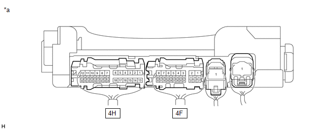
|
*a | Component with harness connected
(Instrument Panel Junction Block Assembly) |
- | - |
Standard Voltage:
|
Tester Connection | Condition |
Specified Condition |
|
4H-35 - Body ground | Engine switch on (IG) |
11 to 14 V |
|
4F-2 - Body ground | Engine switch on (IG) |
11 to 14 V |
|
4F-15 - Body ground | Engine switch on (IG) |
11 to 14 V |
| NG |
| REPLACE INSTRUMENT PANEL JUNCTION BLOCK ASSEMBLY |
|
OK | |
| |
| 5. |
CHECK HARNESS AND CONNECTOR (INSTRUMENT PANEL JUNCTION BLOCK ASSEMBLY - IG2 NO. 1 RELAY) |
(a) Remove the IG2 NO. 1 relay from the No. 1 engine room relay block and No. 1 junction block assembly.
(b) Disconnect the 4F instrument panel junction block assembly connector.
(c) Measure the resistance according to the value(s) in the table below.
Standard Resistance:
|
Tester Connection | Condition |
Specified Condition |
|
4F-13 - No. 1 engine room relay block and No. 1 junction block assembly IG2 NO. 1 relay terminal 1 |
Always | Below 1 Ω |
|
No. 1 engine room relay block and No. 1 junction block assembly IG2 NO. 1 relay terminal 2 - Body ground |
Always | Below 1 Ω |
|
4F-13
or No. 1 engine room relay block and No. 1 junction block assembly IG2
NO. 1 relay terminal 1 - Other terminals and body ground |
Always | 10 kΩ or higher |
| NG |
| REPAIR OR REPLACE HARNESS OR CONNECTOR |
|
OK | |
| |
| 6. |
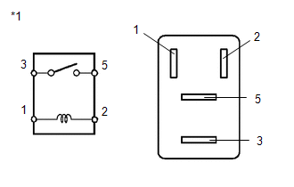
INSPECT IG2 NO. 1 RELAY |
| (a) Measure the resistance according to the value(s) in the table below.
Standard Resistance: |
Tester Connection | Condition |
Specified Condition | |
3 - 5 | Battery voltage not applied between terminals 1 and 2 |
10 kΩ or higher | |
3 - 5 | Battery voltage applied between terminals 1 and 2 |
Below 1 Ω | | |
| OK |
| USE SIMULATION METHOD TO CHECK |
| NG |
| REPLACE IG2 NO. 1 RELAY |
Precaution
PRECAUTION
CAUTION REGARDING INTERFERENCE WITH ELECTRONIC DEVICES
CAUTION:
As
weak radio waves are emitted from the electrical key transmitter
sub-assembly, if a pacemaker is being used, be sure to read the
pacemaker instruction manual and the following.
- People with implantable cardiac pacemakers, cardiac resynchronization
therapy-pacemakers or implantable cardioverter defibrillators should
keep away from the smart key system antennas. The radio waves may affect
the operation of such devices. If necessary, the entry function can be
disabled. Ask your dealer for details, such as the frequency of radio
waves and timing of the emitted radio waves. Then, consult your doctor
to see if you should disable the entry function.
Click here 
- User of any electrical medical device other than implantable cardiac
pacemakers, cardiac resynchronization therapy-pacemakers or implantable
cardioverter defibrillators should consult the manufacturer of the
device for information about its operation under the influence of radio
waves. Radio waves could have unexpected effects on the operation of
such medical devices.
- Ask your dealer for details for disabling the smart key system.
| Exterior antenna |
- Front door outside handle assembly (for Driver Door)
- Front door outside handle assembly (for Front Passenger Door)
- Electrical key antenna (outside luggage compartment)
|
| Interior antenna |
- No. 1 indoor electrical key antenna assembly (front floor)
- No. 1 indoor electrical key antenna assembly (rear floor)
- No. 1 indoor electrical key antenna assembly (inside luggage compartment)
|
HINT:
The smart key system can be disabled by a customize setting.
Click here
PRECAUTION FOR DISCONNECTING CABLE FROM NEGATIVE BATTERY TERMINAL
NOTICE:
When
disconnecting the cable from the negative (-) battery terminal,
initialize the following systems after the cable is reconnected.
|
System Name | See Procedure |
|
Lane Departure Alert System (w/ Steering Control) |
|
|
Intelligent Clearance Sonar System |
|
Parking Assist Monitor System |
|
Panoramic View Monitor System |
|
Pre-collision System |
|
Lighting System (for Gasoline Model with Cornering Light) |
PRECAUTION WHEN USING TECHSTREAM
(a)
When the engine switch is turned off, the DTCs stored in the steering
lock ECU (steering lock actuator or upper bracket assembly) will be
cleared. Be sure to record any output DTCs immediately.
(b)
When using the Techstream with the engine switch off, connect the
Techstream to the DLC3 and turn a courtesy light switch on and off at
intervals of 1.5 seconds or less until communication between the
Techstream and the vehicle begins. Then select the vehicle type under
manual mode and enter the following menus: Body Electrical / Smart Key.
While using the Techstream, periodically turn a courtesy light switch on
and off at intervals of 1.5 seconds or less to maintain communication
between the Techstream and the vehicle.
PRECAUTIONS FOR BATTERY
(a)
If the battery became discharged and then was charged or the cable was
disconnected and reconnected to the (-) battery terminal, the steering
lock may not be released and the engine may not be able to be started
unless the driver door is opened and closed with the engine switch off.
(b)
After the battery is removed and reinstalled, be sure to wait at least
10 seconds before the next engine start. The engine may not start
immediately after the battery is reinstalled.
HINT:
- After disconnecting and reconnecting a cable to the battery, the engine
may not start on the first attempt. If this occurs, turn the engine
switch off. The engine will start normally from the second time onward.
- When a cable to the battery is disconnected and reconnected, the power
source mode returns to the mode it was in before the cable was
disconnected.
PRECAUTION FOR REGISTRATION
(a) If replacing any of the following parts, refer to registration procedure.
Click here
(1) Certification ECU (smart key ECU assembly)
(2) Steering lock ECU (steering lock actuator or upper bracket assembly)
(3) ECM
(4) Electrical key transmitter sub-assembly
(5) Main body ECU (multiplex network body ECU)
(6) DCM (telematics transceiver)*
- *: for Toyota Entune Remote Connect Compatible Type
PRECAUTIONS FOR STEERING LOCK / UNLOCK FUNCTION
(a)
After turning the engine switch off and opening and closing any of the
doors, the steering wheel will be locked due to the steering lock
function. Operating the engine switch again automatically cancels the
steering lock function.
(b) To prevent the steering
lock motor from overheating, the motor operation may be suspended if
the steering is locked and unlocked repeatedly in a short period of
time. In this case, refrain from operating the engine switch. After
about 10 seconds, the steering lock motor will resume functioning.