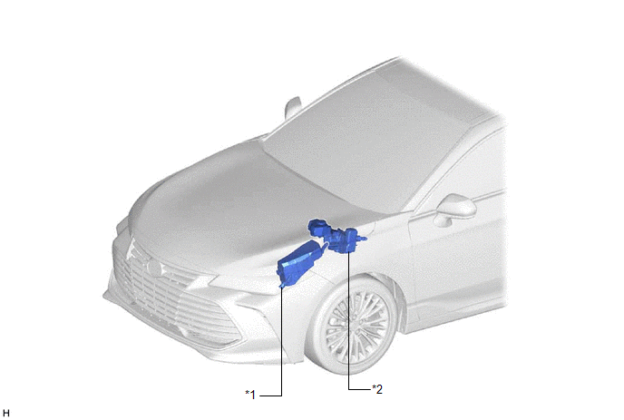
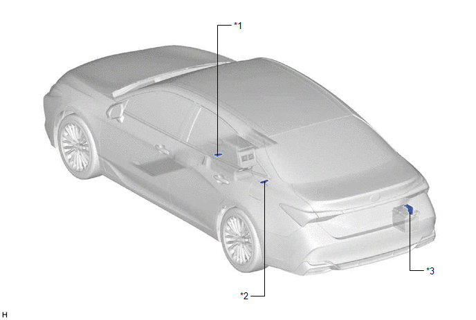
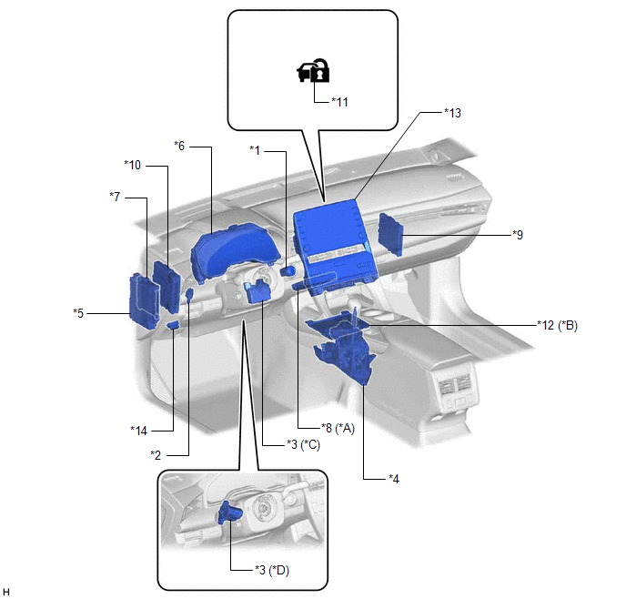
New Key Registration Warning Message is not Displayed
DESCRIPTION
If the new key
registration warning message is not displayed after an electrical key
transmitter sub-assembly has been registered, there may be communication
problem between the certification ECU (smart key ECU assembly) and
combination meter assembly (meter ECU).
CAUTION / NOTICE / HINT
NOTICE:
- When using the Techstream with the power switch off, connect the
Techstream to the DLC3 and turn a courtesy light switch on and off at
intervals of 1.5 seconds or less until communication between the
Techstream and the vehicle begins. Then select the vehicle type under
manual mode and enter the following menus: Body Electrical / Smart Key.
While using the Techstream, periodically turn a courtesy light switch on
and off at intervals of 1.5 seconds or less to maintain communication
between the Techstream and the vehicle.
- The smart key system (for Start Function, HV Model) uses the LIN
communication system and CAN communication system. Inspect the
communication function by following How to Proceed with Troubleshooting.
Troubleshoot the smart key system (for Start Function, HV Model) after
confirming that the communication systems are functioning properly.
Click here 
- Before replacing the certification ECU (smart key ECU assembly), refer to Registration.
Click here 
- After repair, confirm that no DTCs are output.
- Check that there are no electrical key transmitter sub-assemblies in the vehicle.
PROCEDURE
(a) Check for DTCs.
Body Electrical > Smart Key > Trouble Codes
|
Result | Proceed to |
|
DTCs are not output | A |
|
DTCs are output | B |
| B |
 | GO TO DIAGNOSTIC TROUBLE CODE CHART |
|
A |
 | |
| 2. |
READ VALUE USING TECHSTREAM (FL DOOR COURTESY SW) |
(a) Connect the Techstream to the DLC3.
(b) Turn the power switch on (IG).
(c) Turn the Techstream on.
(d) Enter the following menus: Body Electrical / Main Body / Data List.
(e) Read the Data List according to the display on the Techstream.
Body Electrical > Main Body > Data List
|
Tester Display | Measurement Item |
Range | Normal Condition |
Diagnostic Note |
|
FL Door Courtesy SW | Front door LH courtesy light switch signal |
OFF or ON | OFF: Front door LH closed
ON: Front door LH open |
- |
Body Electrical > Main Body > Data List
|
Tester Display |
| FL Door Courtesy SW |
|
Result | Proceed to |
|
On the Techstream screen, ON or OFF is displayed accordingly. |
A |
| On the Techstream screen, ON or OFF is not displayed accordingly. |
B |
| B |
 | GO TO LIGHTING SYSTEM |
|
A |
 | |
| 3. |
CHECK METER / GAUGE SYSTEM |
(a)
With the electrical key transmitter sub-assembly in the vehicle and all
of the doors closed, lock the doors using the entry lock function and
check that the warning message is displayed on the multi-information
display.
NOTICE:
In order to
prevent the electrical key transmitter sub-assembly from being locked
inside the vehicle, perform this inspection with the window of a door
open.
HINT:
Key lock-in prevention function (vehicle interior).
Click here 
|
Result | Proceed to |
|
The warning message is displayed on the multi-information display. |
A |
| The warning message is not displayed on the multi-information display. |
B |
| B |
 | GO TO METER / GAUGE SYSTEM |
|
A |
 | |
| 4. |
ADDITIONAL KEY REGISTRATION |
(a) Clear all of the registered electrical key transmitter sub-assemblies except one and perform registration again.
Click here 
|
NEXT |
 | |
| 5. |
CHECK MULTI-INFORMATION DISPLAY |
(a) With all of the doors closed, lock the doors using the entry lock function.
(b)
Unlock the doors using the entry unlock function, open the driver door
and check that the warning message is displayed on the multi-information
display.
|
Result | Proceed to |
|
The warning message is displayed on the multi-information display. |
A |
| The warning message is not displayed on the multi-information display. |
B |
| A |
 | END (10 DAYS MAY HAVE ELAPSED SINCE AN ELECTRICAL KEY TRANSMITTER SUB-ASSEMBLY WAS REGISTERED) |
| B |
 | REPLACE CERTIFICATION ECU (SMART KEY ECU ASSEMBLY) |
Operation Check
OPERATION CHECK
CHECK CUSTOMIZE PARAMETERS
(a) The operation check below is based on the non-customized initial condition of the vehicle.
Click here 
CHECK PUSH-BUTTON START FUNCTION
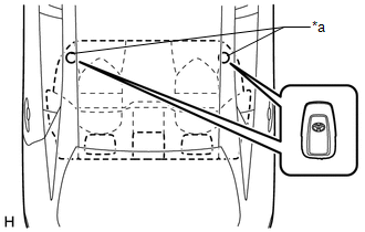
(a) Check the push-button start function:
(1)
Get into the vehicle while carrying the electrical key transmitter
sub-assembly with the power switch off. With the shift lever in P, check
that the key indicator display is displayed when the brake pedal is
depressed. Check that the hybrid control system starts when the power
switch is pressed after the key indicator display is displayed on the
multi-information display.
(2) While carrying the
electrical key transmitter sub-assembly, check that the power source
mode changes in the following order when the power switch is pressed
with the brake pedal released: off → on (ACC) → on (IG) → off.
HINT:
If
the power switch is pressed with the power switch on (IG) and the shift
lever not in P, the power source mode will not change to off, but to on
(ACC).
(3) With the shift lever in P, check that the steering lock operates when a door is opened.
(4)
Check the push-button start function operation range for the front
side. Place the electrical key transmitter sub-assembly at either
inspection point so that it is facing the direction shown in the
illustration, and then check that the hybrid control system can be
started.
NOTICE:
Even if the
electrical key transmitter sub-assembly is in a vehicle interior
detection area, it may not be properly detected if it is on the
instrument panel, in the glove box or on the floor.
HINT:
- Communication may not be possible if the electrical key transmitter
sub-assembly is within 0.2 m (0.656 ft.) of the No. 1 indoor electrical
key antenna assembly (front floor).
Click here 
- Perform this inspection for both inspection points.
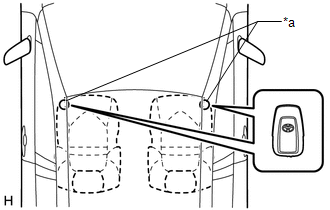
(5)
Check the push-button start function operation range for the rear side.
Place the electrical key transmitter sub-assembly at either inspection
point so that it is facing the direction shown in the illustration, and
then check that the hybrid control system can be started.
NOTICE:
Even
if the electrical key transmitter sub-assembly is in a vehicle interior
detection area, it may not be properly detected if it is on the
instrument panel, in the glove box or on the floor.
HINT:
- Communication may not be possible if the electrical key transmitter
sub-assembly is within 0.2 m (0.656 ft.) of the center of the No. 1
indoor electrical key antenna assembly (rear floor).
Click here 
- Perform this inspection for both inspection points.
CHECK POWER SOURCE MODE CHANGING FUNCTION
(a) Check the power switch.
(1) Check that the power source mode changes according to the chart below.
|
Shift Position | Brake Pedal |
Power Source Mode when Power Switch Pressed |
|
P | Released |
Off → on (ACC) → on (IG) → off |
|
P | Released |
On (READY) → off |
|
P | Released |
On (ACC)* → off |
|
P | Depressed |
Off → on (READY) |
|
P | Depressed |
On (ACC) → on (READY) |
|
P | Depressed |
On (IG) → on (READY) |
|
P | Depressed |
On (READY) → off |
|
P | Depressed |
On (ACC)* → off |
|
Not P | Released |
Off
→ on (ACC) → on (IG) (after power source mode changes to on (IG), power
source mode changes between on (IG) and on (ACC) every time power
switch is pressed) |
| Not P |
Released | On (READY) → on (ACC) |
|
Not P | Depressed |
Off → on (IG) |
|
Not P | Depressed |
On (ACC) → on (IG) |
|
Not P | Depressed |
On (READY) → on (ACC) |
HINT:
*: This situation is only applicable when the power source mode has changed from on (IG) to on (ACC).
CHECK TRANSMITTER BATTERY SAVING MODE FUNCTION
(a) Check the transmitter battery saving mode function:
(1)
Press the unlock switch of the electrical key transmitter sub-assembly
twice while pressing the lock switch and check that the electrical key
transmitter sub-assembly LED blinks 4 times and enters transmitter
battery saving mode.
(2) Check that the smart key system does not operate while in transmitter battery saving mode.
HINT:
To cancel transmitter battery saving mode, press a switch of the electrical key transmitter sub-assembly.
CHECK ENTRY CANCEL FUNCTION
(a) Disable the smart key system and check that all functions of the smart key system no longer operate.
Click here 
HINT:
When
the smart key system is disabled, it is possible to lock and unlock the
doors with the wireless function, and the hybrid control system can be
started by holding the electrical key transmitter sub-assembly near the
power switch.
CHECK KEY DIAGNOSTIC MODE
Click here


