DESCRIPTION
If a new electrical key transmitter sub-assembly could not be registered, wave interference or a malfunction of the certification ECU (smart key ECU assembly), electrical key transmitter sub-assembly, steering lock ECU (steering lock actuator or upper bracket assembly) or door control receiver assembly is suspected.
The registration procedure to add another electrical key transmitter sub-assembly (without replacing any parts) is called "additional key ID registration".
If additional registration is not possible, refer to Additional Key cannot be Registered.
Click here 
HINT:
If any of the following have been performed, registration of all electrical key transmitter sub-assemblies is necessary:WIRING DIAGRAM
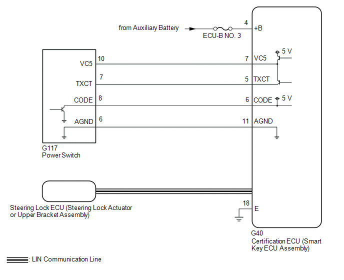
CAUTION / NOTICE / HINT
NOTICE:
Click here
Click here
PROCEDURE
|
1. | CHECK FOR DTC |
(a) Check for DTCs.
Body Electrical > Smart Key > Trouble CodesNOTICE:
If a malfunction occurs, do not remove/install the vehicle auxiliary battery before checking for DTCs.
OK:
DTCs are not output.
| NG |  |
GO TO DIAGNOSTIC TROUBLE CODE CHART |
|
| 2. |
READ VALUE USING TECHSTREAM (NUMBER OF REGISTERED KEY CODES) |
(a) Connect the Techstream to the DLC3.
(b) Turn the power switch on (IG).
(c) Turn the Techstream on.
(d) Enter the following menus: Body Electrical / Smart Key / Data List.
(e) Read the Data List according to the display on the Techstream.
Body Electrical > Smart Key > Data List|
Tester Display | Measurement Item |
Range | Normal Condition |
Diagnostic Note |
|---|---|---|---|---|
|
Number of Registered Key Codes |
Number of registered electrical key transmitter sub-assemblies |
0 to 8 | Number of registered electrical key transmitter sub-assemblies |
Up to 7 electrical key transmitter sub-assemblies can be registered |
|
Tester Display |
|---|
| Number of Registered Key Codes |
HINT:
A new certification ECU (smart key ECU assembly) will be have no electrical key transmitter sub-assemblies registered.
OK:
"0" is displayed on the Techstream display.
| NG | | REPLACE CERTIFICATION ECU (SMART KEY ECU ASSEMBLY) |
|
| 3. |
READ VALUE USING TECHSTREAM (OPERATION HISTORY LIST) |
(a) Enter the following menus: Body Electrical / Smart Key / Utility / Operation History / Registration Function (Reason for Non-operation).
Body Electrical > Smart Key > Utility|
Tester Display |
|---|
| Operation History |
(b) Check the freeze frame data.
Registration Function (Reason for Non-operation):
|
Parameter Name | Detection Condition |
Trouble Area | Proceed to |
|---|---|---|---|
|
Failed Registration Mode |
| Certification ECU (smart key ECU assembly) |
A |
| Vehicle ID not set |
A vehicle ID has not been registered in the certification ECU (smart key ECU assembly). |
Certification ECU (smart key ECU assembly) |
B |
| Key Registration Max |
A registration request is sent when the maximum number of electrical key transmitter sub-assemblies has already been registered. |
Certification ECU (smart key ECU assembly) |
B |
| Vehicle Speed Too High (This applies only when registration fails even though the vehicle is stationary. Make sure that the vehicle is stationary first.) |
A registration request is sent with a vehicle speed of 5 km/h or more. |
Certification ECU (smart key ECU assembly) |
C |
| No ECU Response |
The steering lock ECU (steering lock actuator or upper bracket assembly) was not connected. |
| D |
|
L Code Verification Error | The L codes registered in the certification ECU (smart key ECU assembly) and steering lock ECU (steering lock actuator or upper bracket assembly) did not match. |
| E |
|
Key Verification: Max Number | The number of electrical key transmitter sub-assemblies registered in the certification ECU (smart key ECU assembly) was more than 7. |
Certification ECU (smart key ECU assembly) |
B |
| Key Verification: Amp Abnormal |
Malfunction of the immobiliser amplifier, such as a short to ground. |
| F |
|
Key Verification: Read Error | Although a registered electrical key transmitter sub-assembly was held near the power switch, immobiliser function certification was not successful. |
| G |
|
Unverified Key | Although all of the registered electrical key transmitter sub-assemblies had been held near the power switch, electrical key transmitter sub-assembly registration was not possible due to immobiliser function certification not being successful. |
| H |
|
Transponder Key Amp Error | Malfunction of the immobiliser amplifier, such as a short to ground. |
| F |
|
New Key Registration Error | Although an unregistered electrical key transmitter sub-assembly was held near the power switch, electrical key transmitter sub-assembly registration is not possible due to immobiliser function certification not being successful. |
| I |
|
New Key Vehicle ID Error | Although an unregistered electrical key transmitter sub-assembly was held near the power switch, electrical key transmitter sub-assembly registration is not possible due to the vehicle ID not being stored successfully. |
| I |
|
New Key Registration Failed | After successful immobiliser function certification, time expired before smart recognition completion confirmation or a registration cancellation request was sent. |
| I |
|
New Key Already Registered | Although a registered electrical key transmitter sub-assembly was held near the power switch, time expired or a registration cancellation request was sent. | Certification ECU (smart key ECU assembly) |
J |
| New Key ID Code Error |
Electrical key transmitter sub-assembly registration was not possible due to the certification ECU (smart key ECU assembly) not being able to store the information of the electrical key transmitter sub-assembly to EEPROM correctly. | Certification ECU (smart key ECU assembly) |
B |
| No Response Registering L/S Code |
The certification ECU (smart key ECU assembly) or steering lock ECU (steering lock actuator or upper bracket assembly) was not connected. |
| D |
|
L Code Verification NG | The L code could not be stored by the steering lock ECU (steering lock actuator or upper bracket assembly). |
| E |
|
Key Number Write Error | The certification ECU (smart key ECU assembly) could not store the number of electrical key transmitter sub-assemblies to EEPROM. |
Certification ECU (smart key ECU assembly) |
B |
| ID Code BOX Write Error |
The certification ECU (smart key ECU assembly) could not store the information of whether the ID code box was provided in the vehicle to EEPROM. | Certification ECU (smart key ECU assembly) |
B |
| B |
| REPLACE CERTIFICATION ECU (SMART KEY ECU ASSEMBLY) |
| C |
| GO TO STEP 5 |
| D |
| CHECK FOR DTC B2785 |
| E |
| GO TO STEP 6 |
| F |
| CHECK FOR DTC B278A or B2784 |
| G |
| GO TO STEP 7 |
| H |
| GO TO STEP 11 |
| I |
| GO TO STEP 13 |
| J |
| NEW KEY REGISTRATION FAILED, CHECK THE KEY |
|
| 4. |
CHECK REGISTRATION MODE |
(a) Make sure that another mode or different registration mode is not selected.
OK:
Another mode or a different registration mode is not selected.
HINT:
If any mode has been selected, it is necessary to cancel the mode.
| OK | | REPLACE CERTIFICATION ECU (SMART KEY ECU ASSEMBLY) |
| NG | | PERFORM REREGISTRATION |
| 5. |
READ VALUE USING TECHSTREAM (VEHICLE SPEED METER) |
(a) Connect the Techstream to the DLC3.
(b) Turn the power switch on (IG).
(c) Turn the Techstream on.
(d) Enter the following menus: Body Electrical / Combination Meter / Data List.
(e) Read the Data List according to the display on the Techstream.
Body Electrical > Combination Meter > Data List|
Tester Display | Measurement Item |
Range | Normal Condition |
Diagnostic Note |
|---|---|---|---|---|
|
Vehicle Speed Meter | Vehicle speed |
Min.: 0, Max.: 255 | Almost same as actual vehicle speed (Speedometer tester) |
- |
|
Tester Display |
|---|
| Vehicle Speed Meter |
OK:
"0 km/h (0 mph)" is displayed when the vehicle is stationary.
| OK | | REPLACE CERTIFICATION ECU (SMART KEY ECU ASSEMBLY) |
| NG | | GO TO METER / GAUGE SYSTEM |
| 6. |
REPLACE CERTIFICATION ECU (SMART KEY ECU ASSEMBLY) |
(a) Temporarily replace the certification ECU (smart key ECU assembly) with a new one and register the electrical key transmitter sub-assemblies.
HINT:
Click here
Click here
OK:
All of the electrical key transmitter sub-assemblies could be registered to the new certification ECU (smart key ECU assembly) successfully.
| OK | | END (CERTIFICATION ECU (SMART KEY ECU ASSEMBLY) WAS DEFECTIVE) |
| NG | | REPLACE STEERING LOCK ECU (STEERING LOCK ACTUATOR OR UPPER BRACKET ASSEMBLY) |
| 7. |
CHECK ELECTRICAL KEY TRANSMITTER SUB-ASSEMBLY |
(a) Make sure that a registered electrical key transmitter sub-assembly is being used.
OK:
A registered electrical key transmitter sub-assembly is being used.
| NG | | USE A REGISTERED ELECTRICAL KEY TRANSMITTER SUB-ASSEMBLY AND PERFORM REREGISTRATION |
|
| 8. |
CHECK NUMBER OF REGISTERED ELECTRICAL KEY TRANSMITTER SUB-ASSEMBLIES |
(a) Check the number of registered electrical key transmitter sub-assemblies.
|
Result | Proceed to |
|---|---|
|
Only one electrical key transmitter sub-assembly is registered |
A |
| 2 or more electrical key transmitter sub-assemblies are registered |
B |
| A |
| GO TO STEP 10 |
|
| 9. |
REREGISTRATION |
(a) Reregister the electrical key transmitter sub-assemblies using different order combinations.
Click here
HINT:
If there are 2 or more electrical key transmitter sub-assemblies, make sure that the number of order combinations is the same as the number of electrical key transmitter sub-assemblies so that each transmitter can be checked first.
Example: When there are 3 registered electrical key transmitter sub-assemblies (A, B and C).|
Combination | Order* |
|---|---|
|
1 | A → B → C |
|
2 | B → C→ A |
|
3 | C → A → B |
OK:
"Key Verification: Read Error" is not displayed.
| OK | | REPLACE ELECTRICAL KEY TRANSMITTER SUB-ASSEMBLY (ELECTRICAL KEY TRANSMITTER SUB-ASSEMBLY HELD WHEN "Key Verification: Read Error" WAS DETECTED WAS DEFECTIVE) |
|
| 10. |
REPLACE CERTIFICATION ECU (SMART KEY ECU ASSEMBLY) |
(a) Temporarily replace the certification ECU (smart key ECU assembly) with a new one and register the electrical key transmitter sub-assemblies.
HINT:
Click here
Click here
OK:
All of the electrical key transmitter sub-assemblies could be registered to the new certification ECU (smart key ECU assembly) successfully.
| OK | | END (CERTIFICATION ECU (SMART KEY ECU ASSEMBLY) WAS DEFECTIVE) |
| NG | | REPLACE ELECTRICAL KEY TRANSMITTER SUB-ASSEMBLY |
| 11. |
CHECK FOR ELECTRICAL KEY TRANSMITTER SUB-ASSEMBLY |
(a) Check that all registered electrical key transmitter sub-assemblies are available.
OK:
No registered electrical key transmitter sub-assemblies are missing.
| NG | | ERASE ALL REGISTERED ELECTRICAL KEY TRANSMITTERS EXCEPT ONE, THEN REGISTER THE REMAINING ELECTRICAL KEY TRANSMITTERS |
|
| 12. |
REREGISTRATION |
(a) Register the electrical key transmitter sub-assemblies using different order combinations.
Click here
HINT:
If there are 2 or more electrical key transmitter sub-assemblies, make sure that the number of order combinations is the same as the number of electrical key transmitter sub-assemblies so that each transmitter can be checked first.
Example: When there are 3 registered electrical key transmitter sub-assemblies (A, B and C).|
Combination | Order* |
|---|---|
|
1 | A → B → C |
|
2 | B → C→ A |
|
3 | C → A → B |
OK:
"Key Verification: Read Error" is not displayed.
| OK | | REPLACE CERTIFICATION ECU (SMART KEY ECU ASSEMBLY) |
| NG | | REPLACE ELECTRICAL KEY TRANSMITTER SUB-ASSEMBLY (ELECTRICAL KEY TRANSMITTER SUB-ASSEMBLY HELD WHEN "Key Verification: Read Error" WAS DETECTED WAS DEFECTIVE) |
|
13. | REREGISTRATION |
(a) Using an unregistered electrical key transmitter sub-assembly, register the ID.
Click here
OK:
The key ID can be registered.
| OK | | END (ELECTRICAL KEY TRANSMITTER WAS DEFECTIVE) |
| NG | | REPLACE CERTIFICATION ECU (SMART KEY ECU ASSEMBLY) |
 Dtc Check / Clear. How To Proceed With Troubleshooting. Immobiliser System does not Operate Properly
Toyota Avalon (XX50) 2019-2022 Service & Repair Manual > P710 Hybrid Transmission / Transaxle: Shift Lever
Components COMPONENTS ILLUSTRATION *1 SHIFT LOCK RELEASE BUTTON COVER *2 SHIFT LEVER KNOB SUB-ASSEMBLY *3 TRANSMISSION CONTROL CABLE ASSEMBLY *4 TRANSMISSION FLOOR SHIFT ASSEMBLY *5 NO. 1 CONSOLE BOX DUCT *6 REAR UPPER CONSOLE PANEL SUB-ASSEMBLY N*m (kgf*cm, ft.*lbf): Specified torque - - ILLUSTRATI ...


