Components
COMPONENTS
ILLUSTRATION
|
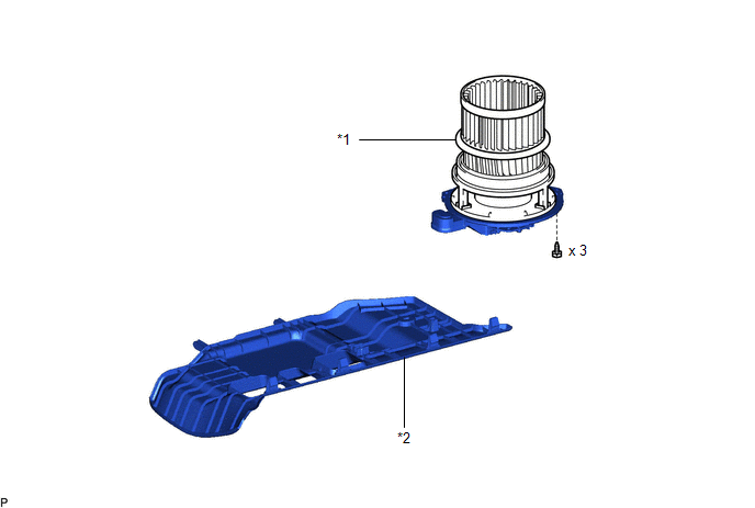
*1 | BLOWER MOTOR WITH FAN SUB-ASSEMBLY |
*2 | NO. 2 INSTRUMENT PANEL UNDER COVER SUB-ASSEMBLY |
Installation
INSTALLATION
PROCEDURE
1. INSTALL BLOWER MOTOR WITH FAN SUB-ASSEMBLY
(a) Install the blower motor with fan sub-assembly with the 3 screws.
NOTICE:
Replace the blower motor with fan sub-assembly if it has been dropped or subjected to a severe impact.
(b) Connect the connector.
2. INSTALL NO. 2 INSTRUMENT PANEL UNDER COVER SUB-ASSEMBLY
Click here 
Removal
REMOVAL
PROCEDURE
1. REMOVE NO. 2 INSTRUMENT PANEL UNDER COVER SUB-ASSEMBLY
Click here

2. REMOVE BLOWER MOTOR WITH FAN SUB-ASSEMBLY
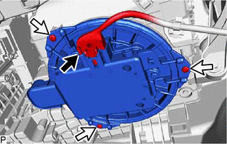
| (a) Disconnect the connector. |
|
(b) Remove the 3 screws and blower motor with fan sub-assembly.
NOTICE:
Replace the blower motor with fan sub-assembly if it has been dropped or subjected to a severe impact.
Toyota Avalon (XX50) 2019-2022 Service & Repair Manual > Audio And Visual System(for Gasoline Model): Speaker Output Short (B15C3)
DESCRIPTION This DTC is stored when a malfunction occurs in the speakers. DTC No. Detection Item DTC Detection Condition Trouble Area B15C3 Speaker Output Short A short is detected in the speaker output circuit Harness or connector Speaker Radio and display receiver assembly*1 Stereo Component Ampli ...