Components
COMPONENTS
ILLUSTRATION
|
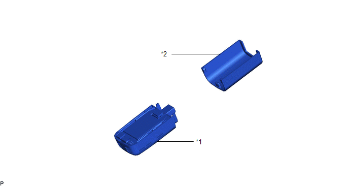
*1 | AIR CONDITIONING THERMISTOR ASSEMBLY |
*2 | SENSOR COVER |
Installation
INSTALLATION
PROCEDURE
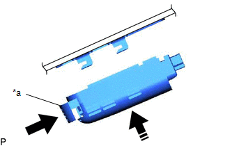
1. INSTALL AIR CONDITIONING THERMISTOR ASSEMBLY
(a) Temporarily install the air conditioning thermistor assembly to the windshield glass as shown in the illustration.
|
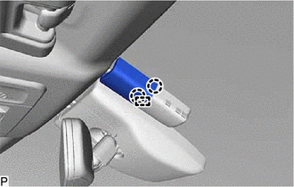
*a | Stopper |
 |
Lock |
 |
Install in this Direction |
(b) Push in the stopper to install the air conditioning thermistor assembly as shown in the illustration.
(c) Connect the connector.
2. INSTALL SENSOR COVER
| (a) Engage the guide and 2 claws to install the sensor cover. |
|
Removal
REMOVAL
PROCEDURE
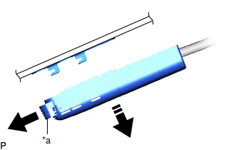
1. REMOVE SENSOR COVER
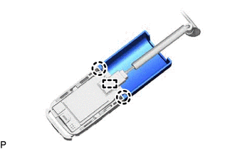
(a) Release the stopper by pulling it out as shown in the illustration.
|
*a | Stopper |
 |
Release |
 |
Remove in this Direction |
(b) Disconnect the air conditioning thermistor assembly with sensor cover from the windshield glass as shown in the illustration.
| (c) Disengage the 2 claws and guide to remove the sensor cover. |
|
2. REMOVE AIR CONDITIONING THERMISTOR ASSEMBLY
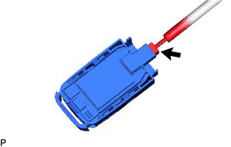
| (a) Disconnect the connector to remove the air conditioning thermistor assembly. |
|
Toyota Avalon (XX50) 2019-2022 Service & Repair Manual > Audio And Visual System(for Gasoline Model): Voice Guidance does not Function. Voice is not Recognized
Voice Guidance does not Function CAUTION / NOTICE / HINT NOTICE: Depending on the parts that are replaced during vehicle inspection or maintenance, performing initialization, registration or calibration may be needed. Refer to Precaution for Audio and Visual System. Click here When replacing the rad ...