Components
COMPONENTS
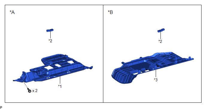
ILLUSTRATION
|
*A | for Driver Side |
*B | for Front Passenger Side |
|
*1 | NO. 1 INSTRUMENT PANEL UNDER COVER SUB-ASSEMBLY |
*2 | NO. 1 INTERIOR ILLUMINATION LIGHT ASSEMBLY |
|
*3 | NO. 2 INSTRUMENT PANEL UNDER COVER SUB-ASSEMBLY |
- | - |
Inspection
INSPECTION
PROCEDURE
1. INSPECT NO. 1 INTERIOR ILLUMINATION LIGHT ASSEMBLY
|
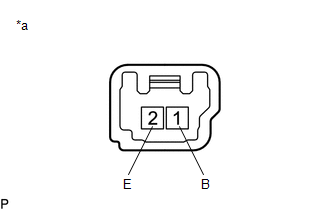
*a | Component without harness connected (No. 1 Interior Illumination Light Assembly) |
(a) Apply auxiliary battery voltage to the No. 1 interior illumination light assembly and check that the light illuminates.
OK:
|
Measurement Condition | Specified Condition |
|---|---|
|
Auxiliary battery positive (+) → 1 (B) Auxiliary battery negative (-) → 2 (E) |
Front footwell light illuminates |
If the result is not as specified, replace the No. 1 interior illumination light assembly.
Installation
INSTALLATION
PROCEDURE
1. INSTALL NO. 1 INTERIOR ILLUMINATION LIGHT ASSEMBLY
(a) Engage the 2 claws to install the No. 1 interior illumination light assembly.
2. INSTALL NO. 1 INSTRUMENT PANEL UNDER COVER SUB-ASSEMBLY (for Driver Side)
Click here 
3. INSTALL NO. 2 INSTRUMENT PANEL UNDER COVER SUB-ASSEMBLY (for Front Passenger Side)
Click here
Removal
REMOVAL
PROCEDURE
1. REMOVE NO. 1 INSTRUMENT PANEL UNDER COVER SUB-ASSEMBLY (for Driver Side)
Click here 
2. REMOVE NO. 2 INSTRUMENT PANEL UNDER COVER SUB-ASSEMBLY (for Front Passenger Side)
Click here
3. REMOVE NO. 1 INTERIOR ILLUMINATION LIGHT ASSEMBLY
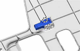
(a) for Driver Side:
| (1) Disengage the 2 claws to remove the No. 1 interior illumination light assembly. |
|
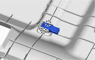
(b) for Front Passenger Side:
| (1) Disengage the 2 claws to remove the No. 1 interior illumination light assembly. |
|
Toyota Avalon (XX50) 2019-2022 Service & Repair Manual > Supplemental Restraint Systems: Knee Airbag Assembly(for Front Passenger Side)
Components COMPONENTS ILLUSTRATION *A for HV Model - - *1 LUGGAGE TRIM SERVICE HOLE COVER - - ILLUSTRATION *1 COWL SIDE TRIM SUB-ASSEMBLY RH *2 FRONT DOOR OPENING TRIM WEATHERSTRIP RH *3 FRONT DOOR SCUFF PLATE RH *4 GLOVE COMPARTMENT PLATE *5 INSTRUMENT PANEL FINISH PANEL END LH *6 INSTRUMENT SIDE P ...