Components
COMPONENTS
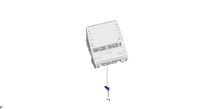
ILLUSTRATION
|
*1 | INTERIOR ILLUMINATION LIGHT SUB-ASSEMBLY |
- | - |
Inspection
INSPECTION
PROCEDURE
1. INSPECT INTERIOR ILLUMINATION LIGHT SUB-ASSEMBLY
|
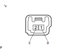
*a | Component without harness connected (Interior Illumination Light Sub-assembly) |
(a) Apply auxiliary battery voltage to the interior illumination light sub-assembly and check that the light illuminates.
OK:
|
Measurement Condition | Specified Condition |
|---|---|
|
Auxiliary battery positive (+) → 1 (B) Auxiliary battery negative (-) → 2 (E) |
Front console light illuminates |
If the result is not as specified, replace the interior illumination light sub-assembly.
Installation
INSTALLATION
PROCEDURE
1. INSTALL INTERIOR ILLUMINATION LIGHT SUB-ASSEMBLY
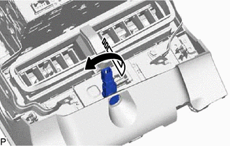
(a) Turn the interior illumination light sub-assembly as shown in the illustration to install it.
 |
Install in this Direction |
2. INSTALL RADIO AND DISPLAY RECEIVER ASSEMBLY WITH BRACKET
Click here 
Removal
REMOVAL
PROCEDURE
1. REMOVE RADIO AND DISPLAY RECEIVER ASSEMBLY WITH BRACKET
Click here

2. REMOVE INTERIOR ILLUMINATION LIGHT SUB-ASSEMBLY
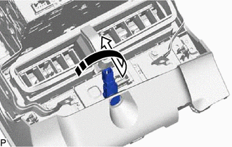
(a) Turn the interior illumination light sub-assembly as shown in the illustration to remove it.
 |
Remove in this Direction |
Toyota Avalon (XX50) 2019-2022 Service & Repair Manual > Electronically Controlled Brake System(for Hv Model): Zero Point Calibration of Yaw Rate Sensor undone (C1210,C1336). SLA Linear Solenoid (C1211,C1212,C1225,C1226). Hydraulic Control System Malfunction (C1214)
Zero Point Calibration of Yaw Rate Sensor undone (C1210,C1336) DESCRIPTION The airbag ECU assembly has a built-in yaw rate and acceleration sensor and detects the vehicle condition using 2 circuits (GL1, GL2). The skid control ECU (brake booster with master cylinder assembly) receives signals from t ...


